Core Solution Concept
Breaks through magnetic saturation limitations, utilizing the electromagnetic induction principle for innovative design. Achieves precise measurement of high-frequency currents, DC components, and high-order harmonics, solving the distortion issues of traditional iron-core CTs in complex waveform scenarios.
Technical Solution Architecture
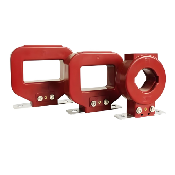
Sensing Unit: Flexible Air-Core Rogowski Coil
Structural Innovations
High-precision enameled wire uniformly wound on a non-magnetic flexible former (e.g., epoxy/engineering plastic)
Split-core mechanical design supporting live installation (suitable for retrofits and confined spaces)
Signal Generation Principle
⚠ Output Signal: di/dt (Current Differential Value)
➡ Directly reflects the current change rate, avoiding core hysteresis effects.
Signal Processing Unit: High-Performance Integrator Circuit
Core Module |
Technical Characteristics |
Performance Indicators |
Integrator Amplifier |
Ultra-low input bias current (≤1pA) |
Temp Drift: ±0.5μV/°C |
Integration Capacitor |
Polypropylene Film Capacitor (C0G grade) |
Capacitance Stability >99%@ -40~125°C |
Dynamic Compensation |
Adaptive feedback network |
Integrator Drift Suppression >40dB |
Bandwidth Extension |
Multi-stage active filtering |
Freq. Response: DC ~ 1MHz |
↳ Output Signal: Vout = k・I(t) (k is calibration factor, voltage linearly corresponds to current)
Core Advantages Over Traditional CTs
Pain Point Scenario |
Limitations of Traditional Iron-Core CTs |
Advantages of This Solution |
High Short-Circuit Current |
Measurement failure due to magnetic saturation |
No magnetic saturation |
DC Component |
Cannot measure steady-state DC |
Supports precise DC component measurement |
High-Frequency Harmonics |
High-frequency signal attenuation due to core losses |
<0.5% distortion @ 100kHz harmonic |
Complex Waveforms |
Phase delay and waveform distortion |
Group Delay <10ns |
Installation Flexibility |
Require power-off installation / Space-constrained |
Flexible split-core design, 3-second deployment |
Typical Application Scenarios
Inverter Output Monitoring
Precisely captures high-frequency oscillations caused by IGBT switching (e.g., 20-150kHz)
Case: Harmonic analysis at a PV inverter plant, measurement error for 50th harmonic (2.5kHz) reduced from 12% to 0.8%.
Arc Fault Detection
Nanosecond response to microsecond-level pulse currents during arc initiation (>100A/μs)
Application: Arc protection in data center distribution cabinets, response time shortened to 300μs.
Electric Locomotive Traction Systems
Simultaneous analysis of DC supply components and PWM carrier signals (carrier freq. 2-5kHz)
Measured Data: Maintained Class 1 accuracy for DC 1500V + 4kHz ripple current.
Key Technical Parameters Summary
Item |
Parameter |
Measurement Range |
10mA ~ 100kA (Peak) |
Frequency Response |
DC – 1.5MHz (-3dB) |
Linearity Error |
≤ ±0.2% FS |
Mounting Bore |
Φ50mm ~ Φ300mm (Customizable) |
Operating Temp. |
-40℃ ~ +85℃ |
Safety Certs. |
IEC 61010, EN 50178 |
Solution Value Summary
Three-Dimensional Technological Breakthroughs:
Physical Layer Innovation: Air-core structure completely eliminates magnetic saturation risk, lifespan increased 10x.
Signal Layer Fidelity: 1MHz bandwidth + sub-microsecond response enables high-precision sensing for Energy IoT.
Engineering Layer Convenience: Split-core design reduces O&M downtime costs by 90%.