I. Solution Background
Facing the urgent demand for low-cost current sensing in industrial control, energy metering, and overcurrent protection applications, traditional electromagnetic current transformers (CTs) and Hall sensors present pain points such as high material costs (especially for >30A specifications) and complex manufacturing processes. This solution employs a four-terminal manganin shunt resistor + optimized signal chain design to achieve extreme cost control in high-volume application scenarios.
II. Core Solution Design
Sensing Unit
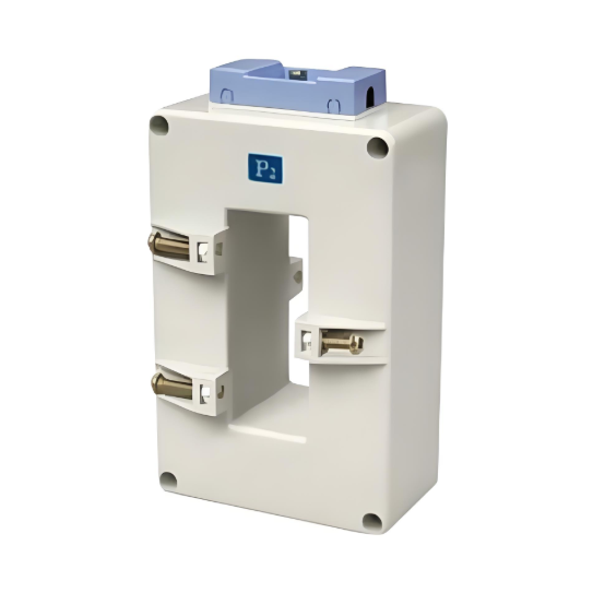
Precision Four-Terminal Manganin Shunt Resistor
Replaces traditional CT core and coil structure.
Key Parameters: 50μΩ-5mΩ resistance range (customized per current rating), Temperature Coefficient <50ppm/°C.
Four-terminal structure eliminates contact resistance error (Kelvin connection).
Signal Processing Chain
Low-Drift Instrumentation Amplifier (INA)
Utilizes devices with <0.5μV/°C offset voltage drift (e.g., AD8237, INA826).
Gain Error <0.1%, CMRR >120dB (suppresses common-mode interference).
Integrated EMI filtering reduces peripheral circuitry.
Isolation Optimization
Switched Capacitor Isolator (e.g., ADI isoPower®)
Replaces traditional CT's magnetic isolation structure.
Supports >5kV DC isolation voltage.
40% lower power consumption, cost only 60% of optocoupler solutions.
Mechanical Design
Injection-Molded Plastic Housing
Eliminates metal shielding layers and potting process.
Maintains IP54 protection rating (dustproof and water splash resistant).
Standardized pluggable terminals for automated assembly.
III. Cost Advantage Analysis (vs. Traditional Solution)
Item |
Traditional CT Solution |
This Shunt Solution |
Reduction/Increase |
100A Sensor BOM Cost |
$8.2 |
$1.7 |
**79%↓** |
Daily Production Line Capacity |
5,000 pcs |
22,000 pcs |
**340%↑** |
Calibration Time/Piece |
45 sec |
8 sec |
**82%↓** |
High-Current Spec Premium |
300% |
20% |
- |
IV. Typical Technical Specifications
Accuracy: 1% FS (@25°C), 2% FS (@-40°C~+85°C)
Bandwidth: DC~50kHz (superior to traditional CT's 10kHz limit)
Rated Current: 15-300A (>300A recommended using parallel shunt arrays)
Power Consumption: <15mW (no self-heating impact)
Response Time: <1μs (significant advantage in overcurrent protection scenarios)
V. Application Scenario Adaptation
Smart Meter Internal Measurement
Suitable for energy metering below Class 1.
Busbar current sampling (paired with Σ-Δ ADC).
Motor Drive Control Systems
Three-phase inverter phase current detection.
Cost-sensitive BLDC controllers.
Overcurrent Protection Devices
Breaker trip current detection.
Response speed improved by 50x.
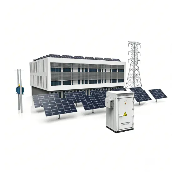
Solar Inverters
String current monitoring (DC side).
Eliminates traditional CT's residual flux error issue.
VI. Implementation Key Points
Thermal Management Design
Copper pour heat dissipation (PCB acts as heat sink).
Rule to follow: ≥4mm² copper pour per 1A current.
EMC Optimization
Differential trace length matching ≤10mm.
π-filter at instrumentation amplifier front end.
Mass Production Control
Fully automated laser resistor trimming calibration.
Temperature compensation coefficient firmware programming.
Dynamic load testing (replaces traditional burn-in process).
Solution Limitations:
Not suitable for >600V strong isolation scenarios (requires reinforced isolation solution).
Significant copper losses at currents >500A (recommend magnetic solution).