• Product
  • Suppliers
  • Manufacturers
  • Solutions
  • Free tools
  • Knowledges
  • Experts
  • Communities
Search


Mesh Current Analysis Method

Edwiin
Field: Power switch
China

The Mesh Current Analysis Method is utilized to analyze and solve electrical networks with multiple sources or circuits comprising numerous meshes (loops) containing voltage or current sources. Also known as the Loop Current Method, this approach involves assuming a distinct current for each loop and determining the polarities of voltage drops across loop elements based on the assumed direction of the loop current.

In mesh current analysis, the unknowns are the currents in different meshes, and the governing principle is Kirchhoff’s Voltage Law (KVL), which states:
"In any closed circuit, the net applied voltage equals the sum of the products of current and resistance. Alternatively, in the direction of current flow, the sum of voltage rises within the loop is equal to the sum of voltage drops."

Let us understand the Mesh Current method with the help of the circuit shown below:

In the Above Network

  • R1, R2, R3, R4, and R5 represent various resistances.

  • V1 and V2 are voltage sources.

  • I1 is the current flowing in mesh ABFEA.

  • I2 is the current flowing in mesh BCGFB.

  • I3 is the current flowing in mesh CDHGC.

  • For simplicity in network analysis, the current direction is assumed to be clockwise in all meshes.

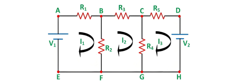
Steps for Solving Networks via Mesh Current Method

Using the circuit diagram above, the following steps outline the mesh current analysis process:

Step 1 – Identify Independent Meshes/Loops

First, identify the independent circuit meshes. The diagram above contains three meshes, which are considered for analysis.

Step 2 – Assign Circulating Currents to Each Mesh

Assign a circulating current to each mesh, as shown in the circuit diagram (I1, I2, I3 flowing in each mesh). To simplify calculations, it is preferable to assign all currents in the same clockwise direction.

Step 3 – Formulate KVL Equations for Each Mesh

Since there are three meshes, three KVL equations will be derived:

Applying KVL to Mesh ABFEA:

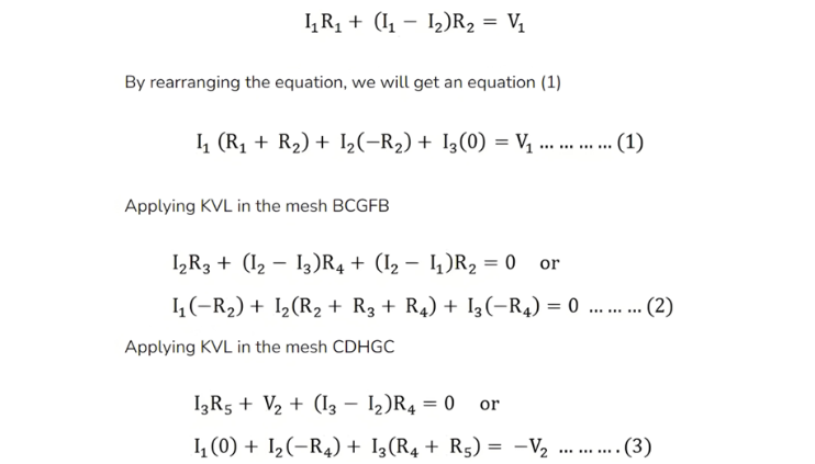
Step 4 – Solve Equations (1), (2), and (3) simultaneously to obtain the values of currents I1, I2, and I3.

With the mesh currents known, various voltages and currents in the circuit can be determined.

Matrix Form

The above circuit can also be solved using the matrix method. The matrix form of Equations (1), (2), and (3) is expressed as:
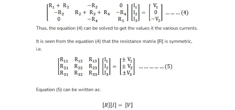
Where,

  • [R] is the mesh resistance

  • [I] is the column vector of mesh currents and

  • [V] is the column vector of the algebraic sum of all the source voltages around the mesh.

This is all about the mesh current analysis method.

Give a tip and encourage the author!

Recommended

Why Must a Transformer Core Be Grounded at Only One Point? Isn't Multi-Point Grounding More Reliable?
Why Does the Transformer Core Need to Be Grounded?During operation, the transformer core, along with the metal structures, parts, and components that fix the core and windings, are all situated in a strong electric field. Under the influence of this electric field, they acquire a relatively high potential with respect to ground. If the core is not grounded, a potential difference will exist between the core and the grounded clamping structures and tank, which may lead to intermittent discharge.I
01/29/2026
Understanding Transformer Neutral Grounding
I. What is a Neutral Point?In transformers and generators, the neutral point is a specific point in the winding where the absolute voltage between this point and each external terminal is equal. In the diagram below, pointOrepresents the neutral point.II. Why Does the Neutral Point Need Grounding?The electrical connection method between the neutral point and earth in a three-phase AC power system is called theneutral grounding method. This grounding method directly affects:The safety, reliabilit
01/29/2026
Voltage Imbalance: Ground Fault, Open Line, or Resonance?
Single-phase grounding, line break (open-phase), and resonance can all cause three-phase voltage unbalance. Correctly distinguishing among them is essential for rapid troubleshooting.Single-Phase GroundingAlthough single-phase grounding causes three-phase voltage unbalance, the line-to-line voltage magnitude remains unchanged. It can be classified into two types: metallic grounding and non-metallic grounding. Inmetallic grounding, the faulted phase voltage drops to zero, while the other two phas
11/08/2025
Composition and Working Principle of Photovoltaic Power Generation Systems
Composition and Working Principle of Photovoltaic (PV) Power Generation SystemsA photovoltaic (PV) power generation system is primarily composed of PV modules, a controller, an inverter, batteries, and other accessories (batteries are not required for grid-connected systems). Based on whether it relies on the public power grid, PV systems are divided into off-grid and grid-connected types. Off-grid systems operate independently without relying on the utility grid. They are equipped with energy-s
10/09/2025
Send inquiry
+86
Click to upload file
Download
Get the IEE Business Application
Use the IEE-Business app to find equipment, obtain solutions, connect with experts, and participate in industry collaboration anytime, anywhere—fully supporting the development of your power projects and business.