Active And Passive Circuit Elements (Components) in Electronics

Electrical4u
03/12/2024

What are Active and Passive Circuit Elements (Components)?

Active and passive components form the two main types of electronic circuit elements. An active component supplies energy to an electric circuit, and hence has the ability to electrically control the flow of charge. A passive component can only receive energy, which it can either dissipate or absorb.

Types of Electronic Components

Electronic elements that make up a circuit are connected together by conductors to form a complete circuit. If these connecting conductors are ideal conductors (i.e. they have no resistance) then all parts of the circuit can be classified into two main categories depending on whether they deliver or absorb energy from the circuit:

  • Active components

  • Passive components

Electrical symbols are used to represent both active and passive components. An example of a basic circuit made up of two electronic elements has been illustrated below:


electric circuit elements


Active Components

An active component is an electronic component which supplies energy to a circuit. Active elements have the ability to electrically control electron flow (i.e. the flow of charge). All electronic circuits must contain at least one active component.

Common examples of active components include:


active passive circuit elements


Voltage Sources

A voltage source is an example of an active component in a circuit. When current leaves from the positive terminal of the voltage source, energy is being supplied to the circuit. As per the definition of an active element, a battery can also be considered as an active element, as it continuously delivers energy to the circuit during discharging.

Current Sources

A current source is also considered an active component. The current supplied to the circuit by an ideal current source is independent of circuit voltage. As a current source is controlling the flow of charge in a circuit, it is classified as an active element.

Transistors

Although not as obvious as a current or voltage source – transistors are also an active circuit component. This is because transistors are able to amplify the power of a signal (see our article on transistors as an amplifier if you want to know exactly how).

As this amplification is essentially controlling the flow of charge – transistors are hence classified as an active component.

Passive Components

A passive component is an electronic component which can only receive energy, which it can either dissipate, absorb or store it in an electric field or a magnetic field. Passive elements do not need any form of electrical power to operate.

As the name ‘passive’ suggests – passive devices do not provide gain or amplification. Passive components cannot amplify, oscillate, or generate an electrical signal.

Common examples of passive components include:

Resistors

A resistor is taken as a passive element since it can not deliver any energy to a circuit. Instead resistors can only recieve energy which they can dissipate as heat as long as current flows through it.


passive circuit element


Inductors

An inductor is also considered as passive element of circuit, because it can store energy in it as a magnetic field, and can deliver that energy to the circuit, but not in continuous basis. The energy absorbing and delivering capacity of an inductor is limited and transient in nature. That is why an inductor is taken as a passive element of a circuit.

Capacitors

A capacitor is considered as a passive element because it can store energy in it as electric field. The energy dealing capacity of a capacitor is limited and transient – it is not actually supplying energy, it is storing it for later use.

As such it is not considered an active component since no energy is being supplied or amplified.

Transformers

A transformer is also a passive electronic component. Although this can seem surprising since transformers are often used to raise voltage levels – remember that power is kept constant.

When transformers step up (or step down) voltage, power and energy remain the same on the primary and secondary side. As energy is not actually being amplified – a transformer is classified as a passive element.


passive and active element


Bilateral Elements

Conduction of current in both directions in a circuit element with same magnitude is termed as a bilateral circuit element. It offers some resistance to current flow in both directions.

Examples: Resistors, inductors, capacitors etc.


bilateral element


This figure shows that a bilateral circuit element can conduct from both sides and offersame resistance for current from either side.

Unilateral Elements

The unilateral circuit element does not offer same resistance to the current of either direction. The resistance of the unilateral circuit element is different for forward current than that of reverse current.

Examples:diode, transistor etc.


unilateral element


The figure above shows a diode as a unilateral circuit element. When diode is forward biased it offers very small resistance and conducts. While it is reverse biased, it offers very high resistance and doesn’t conduct. The circuit element can be categorized in another manner, such as lumped and distributed circuit elements.

Lumped Elements

When the voltage across and current through the element don’t vary with dimension of the element, it is called lumped circuit elements.

Examples: Resistor connected in any electrical circuit.

Distributed Elements

When the voltage across and current through the element change with dimensions of the element, it is called distributed circuit element.

Examples: Resistance of a transmission line. It varies with the length of the line.

Source: Electrical4u.

Statement: Respect the original, good articles worth sharing, if there is infringement please contact delete.

Electrical4u

Electrical4U is dedicated to the teaching and sharing of all things related to electrical and electronics engineering.

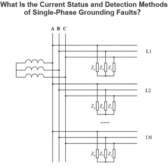
Frequency division method for measuring grid-to-ground insulation parameters
The frequency division method enables the measurement of grid-to-ground parameters by injecting a current signal of a different frequency into the open delta side of the potential transformer (PT).This method is applicable to ungrounded systems; however, when measuring the grid-to-ground parameters of a system where the neutral point is grounded via an arc suppression coil, the arc suppression coil must be disconnected from operation beforehand. Its measurement principle is shown in Figure 1.As
Leon
07/25/2025
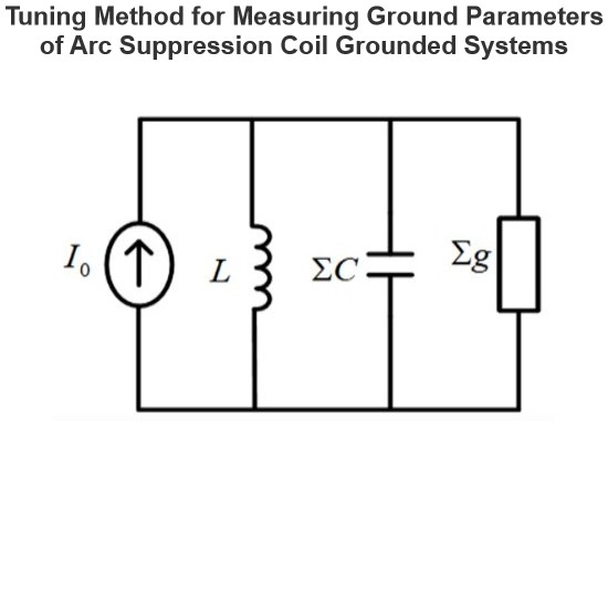
The insulation parameters of the power grid to ground are measured by the tuning method
The tuning method is suitable for measuring the ground parameters of systems where the neutral point is grounded via an arc suppression coil, but not applicable to ungrounded neutral point systems. Its measurement principle involves injecting a current signal with continuously varying frequency from the secondary side of the Potential Transformer (PT), measuring the returned voltage signal, and identifying the system's resonant frequency.During the frequency sweeping process, each injected heter
Leon
07/25/2025
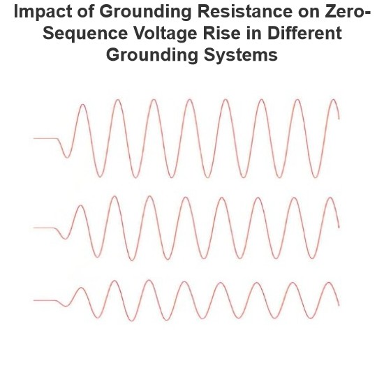
Effect of Transition Resistance at the Grounding Point on the Rising Speed of Zero - sequence Voltage
In an arc - suppression coil grounding system, the rising speed of the zero - sequence voltage is greatly affected by the value of the transition resistance at the grounding point. The larger the transition resistance at the grounding point, the slower the rising speed of the zero - sequence voltage.In an ungrounded system, the transition resistance at the grounding point has basically no impact on the rising speed of the zero - sequence voltage.Simulation Analysis: Arc - suppression Coil Ground
Leon
07/24/2025
Current Division and Voltage Division Rule
Current Division RuleA parallel circuit functions as a current divider, where the incoming current splits among all branches while the voltage across each branch remains constant. The Current Division Rule is used to determine the current through circuit impedances, as illustrated by the circuit below:The currentI splits intoI1 andI2 across two parallel branches with resistancesR1 andR2, whereVdenotes the voltage drop across both resistances. As is known,Then the equation of the current is writt
Edwiin
06/02/2025
Inquiry
Download
IEE-Business is dedicated to serving the personnel in the global power industry.
Join IEE-Business, not only can you discover power equipment and power knowledge, but also canhnd like - minded friends!