Planar and Non-Planar Circuits: Analysis and Applications

Electrical4u
03/12/2024

A planar circuit is a circuit that can be drawn on a flat surface without any wires crossing each other.

planar graph

A non-planar circuit is a circuit that cannot be drawn on a flat surface without any wires crossing each other. Planar and non-planar circuits have different properties and methods of analysis. In this article, we will explain what planar and non-planar circuits are, how to analyze them using graph theory and loop current method, and what are some applications of these circuits in electrical engineering.

What is Graph Theory?

Graph theory is a branch of mathematics that studies the properties and relationships of graphs. A graph is a collection of nodes (also called vertices) and edges (also called branches) that connect the nodes. Graphs can be used to model many phenomena in science, engineering, and social sciences.

One of the applications of graph theory is to represent electrical circuits. Each element in a circuit (such as a resistor, a capacitor, or a voltage source) can be represented by an edge in a graph. Each node in a graph can represent a junction point or a terminal in a circuit. The direction of the current flow in a circuit can be indicated by an arrow on each edge. This type of graph is called an oriented graph.

What is a Planar Circuit?

A planar circuit is a circuit that can be drawn on a flat surface without any wires crossing each other. Equivalently, a planar circuit is a circuit whose oriented graph can be embedded on a plane without any edges crossing each other. A planar circuit has some advantages over a non-planar circuit, such as:

  • It is easier to visualize and draw.

  • It has fewer loops and nodes than a non-planar circuit with the same number of elements.

  • It can be analyzed using mesh analysis or nodal analysis, which are systematic methods based on Kirchhoff’s laws.

What is a Non-Planar Circuit?

A non-planar circuit is a circuit that cannot be drawn on a flat surface without any wires crossing each other.

non-planar graph

Equivalently, a non-planar circuit is a circuit whose oriented graph cannot be embedded on a plane without any edges crossing each other. A non-planar circuit has some disadvantages over a planar circuit, such as:

  • It is harder to visualize and draw.

  • It has more loops and nodes than a planar circuit with the same number of elements.

  • It cannot be analyzed using mesh analysis or nodal analysis, which are only applicable to planar circuits.

How to Analyze Planar and Non-Planar Circuits?

To analyze planar and non-planar circuits, we can use the loop current method, which is based on Kirchhoff’s voltage law (KVL). The loop current method involves the following steps:

  1. Identify all the loops in the circuit. A loop is any closed path that does not contain any other closed path within it. A loop can be either a mesh (a loop that does not contain any other element except those on its boundary) or a super mesh (a loop that contains one or more meshes within it).

  2. Assign loop currents to each loop. A loop current is an imaginary current that flows around the loop in either a clockwise or counterclockwise direction. The direction of the loop current can be chosen arbitrarily, but it must be consistent throughout the analysis.

  3. Write KVL equations for each loop. A KVL equation states that the algebraic sum of the voltages around any closed loop is zero. The voltage across an element depends on its type and polarity, as well as the direction of the loop current relative to the element current.

  4. Solve the system of equations for the unknown loop currents. This can be done using various methods, such as substitution, elimination, matrix inversion, or Cramer’s rule.

  5. Find the element currents and voltages using the loop currents. The element current is equal to the sum or difference of the loop currents passing through it, depending on their directions. The element voltage can be found using Ohm’s law or other relations for different types of elements.

How to Identify Planar and Non-Planar Circuits?

To identify whether a circuit is planar or non-planar, we can use the following criteria:

  • If the circuit can be redrawn without any wires crossing each other, then it is planar.

  • If the circuit cannot be redrawn without any wires crossing each other, then it is non-planar.

    example of a non-planar graph

Sometimes, a circuit may look non-planar at first sight, but it can be redrawn as planar by rearranging some elements or nodes. For example, consider the following circuit.

This circuit looks non-planar because two resistors cross each other.

example of a planar graph

However, if we move one resistor to another position, we can obtain an equivalent planar circuit.

Therefore, this circuit is actually planar.

What are Some Applications of Planar and Non-Planar Circuits?

Planar and non-planar circuits have various applications in electrical engineering, such as:

  • Planar circuits are widely used in printed circuit boards (PCBs), which are thin sheets of insulating material with conductive tracks printed or etched on them. PCBs are used to connect electronic components in devices such as computers, smartphones, radios, etc.

  • Non-planar circuits are often used in three-dimensional (3D) integrated circuits (ICs), which are stacks of multiple layers of electronic components connected by vertical wires or vias.

    3D integrated circuit
  • 3D ICs offer advantages such as higher density, lower power consumption, faster speed, and better performance than conventional 2D ICs.

  • Planar and non-planar circuits can also be used to model various physical phenomena that involve networks or graphs, such as fluid flow, heat transfer, traffic flow, social networks, etc.

Summary

In this article, we have learned about planar and non-planar circuits: what they are, how to analyze them using graph theory and loop current method, and what are some applications of these circuits in electrical engineering.

Some key points to remember are:

  • A planar circuit is a circuit that can be drawn on a flat surface without any wires crossing each other.

  • A non-planar circuit is a circuit that cannot be drawn on a flat surface without any wires crossing each other.

  • Graph theory is a branch of mathematics that studies the properties and relationships of graphs.

  • An oriented graph is a graph with arrows on its edges indicating the direction of current flow in an electrical circuit.

  • The loop current method is based on Kirchhoff’s voltage law (KVL) and involves writing equations for all the loops in a circuit and solving them for the unknown loop currents.

  • Planar circuits can be analyzed using mesh analysis or nodal analysis, which are only applicable to planar circuits.

  • Non-planar circuits require using super meshes or other techniques to analyze them using the loop current method.

  • Planar circuits are widely used in printed circuit boards (PCBs), while non-planar circuits are often used in three-dimensional (3D) integrated circuits (ICs).

Source: Electrical4u.

Statement: Respect the original, good articles worth sharing, if there is infringement please contact delete.

Electrical4u

Electrical4U is dedicated to the teaching and sharing of all things related to electrical and electronics engineering.

Frequency division method for measuring grid-to-ground insulation parameters
The frequency division method enables the measurement of grid-to-ground parameters by injecting a current signal of a different frequency into the open delta side of the potential transformer (PT).This method is applicable to ungrounded systems; however, when measuring the grid-to-ground parameters of a system where the neutral point is grounded via an arc suppression coil, the arc suppression coil must be disconnected from operation beforehand. Its measurement principle is shown in Figure 1.As
Leon
07/25/2025
The insulation parameters of the power grid to ground are measured by the tuning method
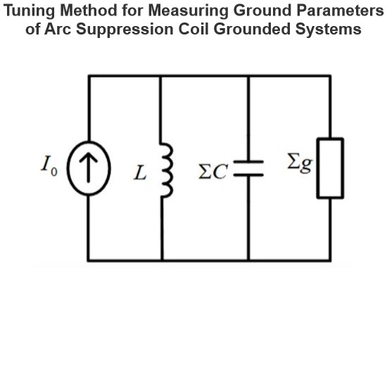
The tuning method is suitable for measuring the ground parameters of systems where the neutral point is grounded via an arc suppression coil, but not applicable to ungrounded neutral point systems. Its measurement principle involves injecting a current signal with continuously varying frequency from the secondary side of the Potential Transformer (PT), measuring the returned voltage signal, and identifying the system's resonant frequency.During the frequency sweeping process, each injected heter
Leon
07/25/2025
Effect of Transition Resistance at the Grounding Point on the Rising Speed of Zero - sequence Voltage
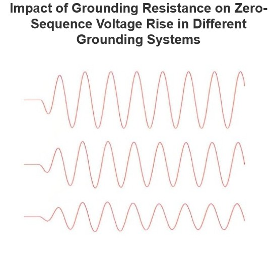
In an arc - suppression coil grounding system, the rising speed of the zero - sequence voltage is greatly affected by the value of the transition resistance at the grounding point. The larger the transition resistance at the grounding point, the slower the rising speed of the zero - sequence voltage.In an ungrounded system, the transition resistance at the grounding point has basically no impact on the rising speed of the zero - sequence voltage.Simulation Analysis: Arc - suppression Coil Ground
Leon
07/24/2025
Current Division and Voltage Division Rule
Current Division RuleA parallel circuit functions as a current divider, where the incoming current splits among all branches while the voltage across each branch remains constant. The Current Division Rule is used to determine the current through circuit impedances, as illustrated by the circuit below:The currentI splits intoI1 andI2 across two parallel branches with resistancesR1 andR2, whereVdenotes the voltage drop across both resistances. As is known,Then the equation of the current is writt
Edwiin
06/02/2025
Inquiry
Download
IEE-Business is dedicated to serving the personnel in the global power industry.
Join IEE-Business, not only can you discover power equipment and power knowledge, but also canhnd like - minded friends!