Reciprocity Theorem

Electrical4u
03/12/2024

What is Reciprocal Property?

In many electrical networks it is found that if the positions of voltage source and ammeter are interchanged, the reading of ammeter remains the same. It is not clear to you. Let’s explain it in details. Suppose a voltage source is connected to a passive network and an ammeter is connected to other part of the network to indicate the response.
Now any one interchanges the positions of ammeter and voltage source that means he or she connects the voltage source at the part of the network where the ammeter was connected and connects ammeter to that part of the network where the voltage source was connected.

The response of the ammeter means current through the ammeter would be the same in both the cases. This is where the property of reciprocity comes in the circuit. The particular circuit that has this reciprocal property, is called reciprocal circuit. This type of circuit perfectly obeys reciprocity theorem.

Explanation of Reciprocity Theorem

The voltage source and the ammeter used in this theorem must be ideal. That means the internal resistance of both the voltage source and ammetermust be zero. The reciprocal circuit may be a simple or complex network. But every complex reciprocal passive network can be simplified into a simple network. As per reciprocity theorem, in a linear passive network, supply voltage V and output current I are mutually transferable.

The ratio of V and I is called the transfer resistance. The theorem can easily be understood by this following example.
reciprocity theorem

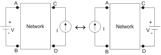
Source: Electrical4u.

Statement: Respect the original, good articles worth sharing, if there is infringement please contact delete.


Electrical4u

Electrical4U is dedicated to the teaching and sharing of all things related to electrical and electronics engineering.

Frequency division method for measuring grid-to-ground insulation parameters
The frequency division method enables the measurement of grid-to-ground parameters by injecting a current signal of a different frequency into the open delta side of the potential transformer (PT).This method is applicable to ungrounded systems; however, when measuring the grid-to-ground parameters of a system where the neutral point is grounded via an arc suppression coil, the arc suppression coil must be disconnected from operation beforehand. Its measurement principle is shown in Figure 1.As
Leon
07/25/2025
The insulation parameters of the power grid to ground are measured by the tuning method
The tuning method is suitable for measuring the ground parameters of systems where the neutral point is grounded via an arc suppression coil, but not applicable to ungrounded neutral point systems. Its measurement principle involves injecting a current signal with continuously varying frequency from the secondary side of the Potential Transformer (PT), measuring the returned voltage signal, and identifying the system's resonant frequency.During the frequency sweeping process, each injected heter
Leon
07/25/2025
Effect of Transition Resistance at the Grounding Point on the Rising Speed of Zero - sequence Voltage
In an arc - suppression coil grounding system, the rising speed of the zero - sequence voltage is greatly affected by the value of the transition resistance at the grounding point. The larger the transition resistance at the grounding point, the slower the rising speed of the zero - sequence voltage.In an ungrounded system, the transition resistance at the grounding point has basically no impact on the rising speed of the zero - sequence voltage.Simulation Analysis: Arc - suppression Coil Ground
Leon
07/24/2025
Current Division and Voltage Division Rule
Current Division RuleA parallel circuit functions as a current divider, where the incoming current splits among all branches while the voltage across each branch remains constant. The Current Division Rule is used to determine the current through circuit impedances, as illustrated by the circuit below:The currentI splits intoI1 andI2 across two parallel branches with resistancesR1 andR2, whereVdenotes the voltage drop across both resistances. As is known,Then the equation of the current is writt
Edwiin
06/02/2025
Inquiry
Download
IEE-Business is dedicated to serving the personnel in the global power industry.
Join IEE-Business, not only can you discover power equipment and power knowledge, but also canhnd like - minded friends!