Motor Thermal Overload Protection

Encyclopedia
09/11/2024

Motor thermal overload protection set


Thermal overload protection is a safety mechanism that prevents the motor from overheating by detecting excessive current and stopping the motor.


Cause of overheating


When considering motor overheating, the first cause that comes to mind is overload. Mechanical overload causes the motor to consume a higher current, which leads to overheating. If the rotor is locked by external forces, consuming too much current, the motor will also overheat. Low supply voltage is another reason; The motor consumes more current to maintain torque. When one power supply phase fails, the single phase and the power supply are unbalanced, resulting in negative sequence current, which can also lead to overheating. When the motor accelerates to its rated speed, the sudden loss and recovery of voltage can lead to overheating, which consumes a large current.


Since thermal overload or overheating of the motor can lead to insulation failure and winding damage, for proper motor thermal overload protection, the motor should be protected from the following conditions


  • Mechanical overload

  • Motor shaft is blocked

  • Low supply voltage

  • Single-phase power supply

  • Power unbalance

  • Sudden loss and reconstruction of supply voltage


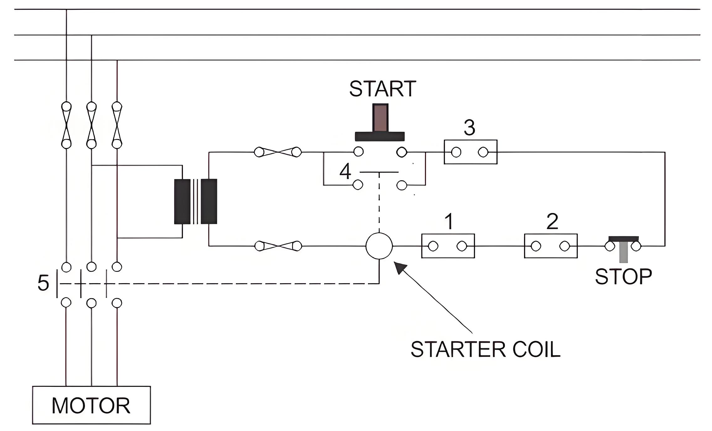
The most basic protection scheme of the motor is thermal overload protection, which mainly covers the protection of all the above situations. In order to understand the basic principle of thermal overload protection, let's look at the schematic diagram of the basic motor control scheme.


In the figure above, when the START push is closed, the start coil is energized through the transformer. When the starting coil is energized, the normally open (NO) contact 5 closes, so the motor obtains the supply voltage at its terminals and begins to rotate. The START coil also closes contact 4, energizing the start coil even if the Start button contact is released from its closed position.


 To stop the motor, there are several normally closed (NC) contacts in series with the starting coil, as shown in the figure. One of them is the STOP button contact. If the STOP button is pressed, this button contact will open and disconnect the continuity of the starting coil circuit, resulting in a power failure of the starting coil. 


Thus, contacts 5 and 4 return to their normal open positions. Then, in the absence of voltage at the motor terminals, it will eventually stop running. Similarly, any other NC contacts (1, 2, and 3), if opened, are connected in series with the starting coil; It will also stop the motor. These NC contacts are electrically coupled with various protective relays to stop the operation of the motor under different abnormal conditions


f37533a319f786320626fb5f0d1441af.jpeg


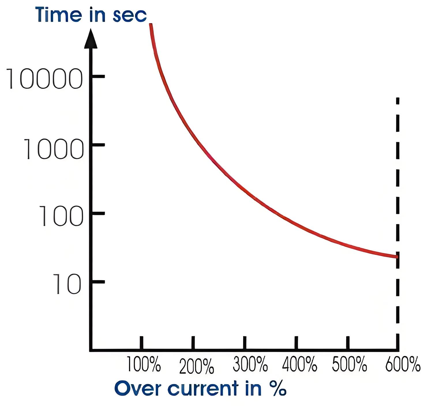
Another important point of motor thermal overload protection is the predetermined overload tolerance value of the motor. Each motor can operate for a period of time in excess of its rated load according to load conditions specified by the manufacturer. This relationship between motor load and safe operating time is shown in the thermal limit curve. Here is an example of such a curve.


Here the Y-axis or the vertical axis represents the allowable time in seconds, and the X-axis or the horizontal axis represents the overload percentage. It is clear from the curve that the motor can operate safely at 100% rated load for a long time without causing any damage due to overheating. It can operate safely for 1000 seconds at 200% of its normal rated load. It can operate safely for 100 seconds at 300% of normal rated load. 


It can operate safely for 600 seconds at 15% of its normal rated load. The top half of the curve indicates the normal operating conditions of the rotor, and the bottom half indicates the mechanical locking state of the rotor


3e74341d4f3d16ded26a8b6720277946.jpeg

7e07b7c9d6fe0766a1dd245ba3165ab2.jpeg

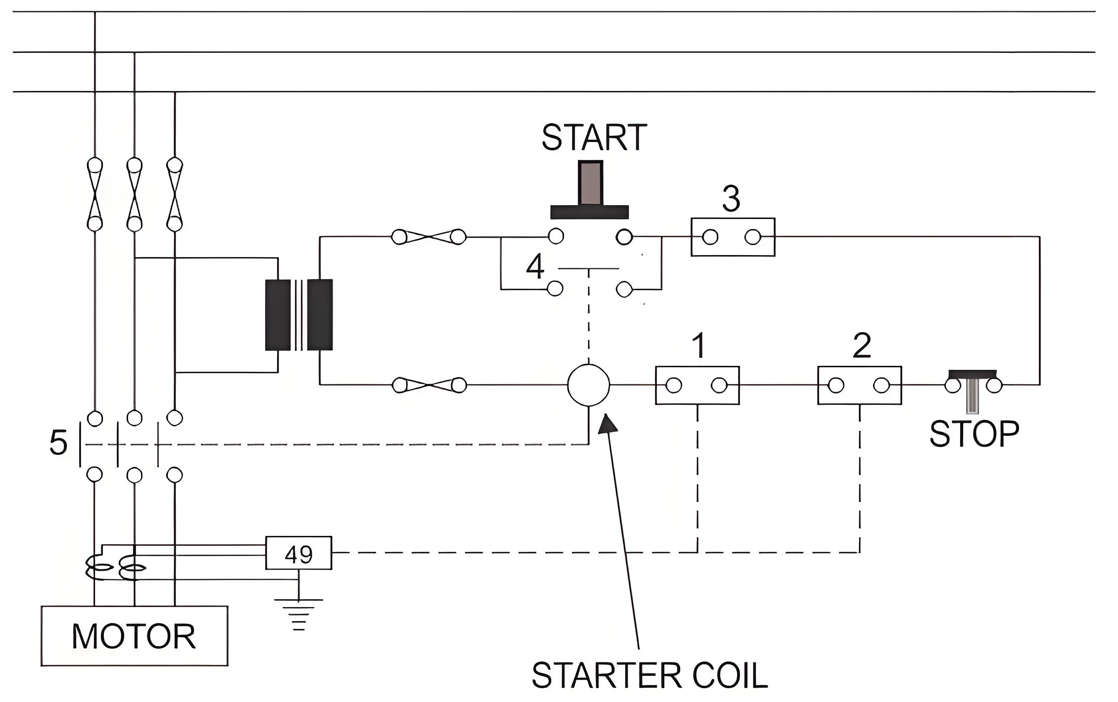
Thermal overload relay


The relay uses bimetal sheets that heat up and bend when the current is too high, breaking the circuit to stop the motor.


Thermal limiting curve


This curve shows how long the motor can operate at different overload levels without damage, helping to set protection limits.


RTD Advanced protection


Resistance temperature detectors (RTDS) provide precise motor protection by monitoring temperature changes and triggering protection measures.


Encyclopedia

The Electricity Encyclopedia is dedicated to accelerating the dissemination and application of electricity knowledge and adding impetus to the development and innovation of the electricity industry.

What is Voltage Stability in Power Systems?
Definition of Voltage StabilityVoltage stability in a power system is defined as the ability to maintain acceptable voltages at all buses under both normal operating conditions and after being subjected to a disturbance. In normal operation, the system’s voltages remain stable; however, when a fault or disturbance occurs, voltage instability may arise, leading to a progressive and uncontrollable voltage decline. Voltage stability is sometimes referred to as "load stability."Voltage instability c
Encyclopedia
07/26/2025
What is Dual Trace Oscilloscope?
What is Dual Trace Oscilloscope?DefinitionA dual-trace oscilloscope uses a single electron beam to generate two separate traces, each deflected by an independent input source. To produce these two traces, it primarily employs two operating modes—alternate mode and chopped mode—controlled by a switch.Purpose of a Dual-Trace OscilloscopeWhen analyzing or studying multiple electronic circuits, comparing their voltage characteristics is often critical. While one could use multiple oscilloscopes for
Encyclopedia
07/25/2025
What is Cathode Ray Oscilloscope (CRO)?
What is Cathode Ray Oscilloscope (CRO)?DefinitionA cathode ray oscilloscope (CRO) is an electrical instrument for measuring, analyzing and visualizing waveforms and other electronic/electrical phenomena. As a high - speed X - Y plotter, it shows an input signal against another signal or time. Capable of analyzing waveforms, transient phenomena and time - varying quantities across a wide frequency range (from very low to radio frequencies), it mainly operates on voltage. Other physical quantities
Edwiin
07/25/2025
What is Automatic Voltage Regulator?
An automatic voltage regulator is employed to regulate voltage, converting fluctuating voltages into a constant one. Voltage fluctuations mainly stem from variations in the load on the supply system. Such voltage variations can damage the equipment within the power system. These fluctuations can be mitigated by installing voltage - control equipment at various locations, such as near transformers, generators, and feeders. Multiple voltage regulators are often placed throughout the power system t
Edwiin
05/22/2025
Inquiry
Download
IEE-Business is dedicated to serving the personnel in the global power industry.
Join IEE-Business, not only can you discover power equipment and power knowledge, but also canhnd like - minded friends!