An GIS Equipment Explosion Accident Caused by PT Secondary Wiring Errors

Felix Spark
07/08/2025

1. Accident Overview
A newly - built 110kV substation’s GIS exploded during commissioning due to a PT secondary circuit short - circuit. Though the cause was simple, consequences were severe, warranting reflection.
2. Accident Process
On the power - transmission day:
  • The upper - level power supply charged the 110kV GIS (a combined appliance).
  • 20s after closing the incoming switch and first live - impacting the 110kV bus, white smoke emerged between the PT compartment and control cabinet.
  • Within ten seconds, the bus PT’s GIS compartment exploded. The upper power tripped; the PT compartment’s disc insulator burst, filling the GIS room with insulator fragments and SF₆ combustion by - products.
3. Cause Analysis
3.1 On - site Investigation
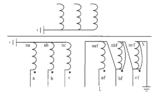
The 110kV PT (Shanghai MWB, electromagnetic type) had:
  • 1 basic secondary winding: 100/√3 V (150VA, 0.2 class).
  • 1 auxiliary secondary winding: 100V (150VA, 3P class), unused per design (routed to the control cabinet terminal block, no external connection).
Key findings:
  • Phase C: Severe PT secondary winding insulation burns; basic winding conductor charred. Auxiliary winding conductor insulation totally burned; insulation cylinder between auxiliary winding & iron core charred. Insulation resistance between basic & auxiliary windings = 0.
  • Phase B: Basic secondary winding outer insulation had burning marks; internal paint film intact. Auxiliary winding surface insulation showed overheating charring.
  • Phase A: Slight basic secondary winding surface insulation burn; other conductors/insulation intact.

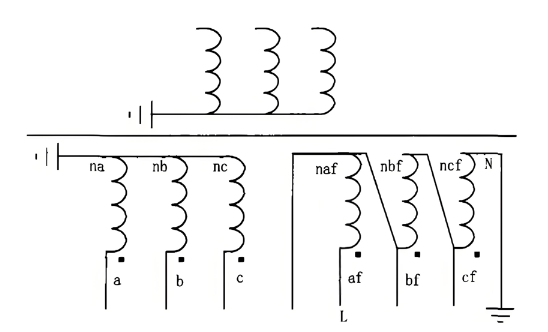
Preliminary conclusion: PT secondary circuit short - circuit, likely in B/C phase auxiliary windings.
Further control cabinet inspection: B/C phase auxiliary windings were shorted inside. Design - intended connections (C - ncf to terminal 11, B - nbf to terminal 15) were misrouted (C - ncf to 12, shorting to 14 - cf; B - nbf to 16, shorting to 18 - bf).
3.2 Accident Development
  • Short - circuit start: After primary system closure, B/C phase auxiliary windings (cf, ncf; bf, nbf) shorted → B/C voltage drop.
  • B phase short - circuit end: After 20s, B phase short - circuit disconnected (primary lead burned by arc). Short time caused only B auxiliary winding overheating.
  • C phase consequence: 43s short - circuit (per accident recording) overheated C phase secondary conductor → insulation melt/char. White smoke came from this.
  • Insulation failure: PT auxiliary winding insulation melt degraded SF₆ gas in the PT chamber → lower insulation level.
  • Discharges: Reduced insulation + close phase - to - ground distances → A/B/C phases discharged to GIS shell.
  • Explosion: Arc energy raised gas chamber pressure → PT disc insulator burst.

3.3 Human Error
During commissioning:
  • Technicians rechecked PT polarity/insulation.
  • For convenience, they removed the PT secondary circuit from the control cabinet terminal block.
  • Mistakenly shorted B/C phase auxiliary winding ends; failed to verify → B/C auxiliary windings shorted.
4. Preventive Measures
4.1 PT Secondary Circuit Safety
Short - circuits in PT secondary circuits damage components or burn PTs. Installed in a closed GIS chamber, PT faults cause explosions (risking injury, delaying repairs). Thus, GIS PT installation/wiring demands strict attention.
4.2 Secondary Circuit Protocols
“Electrical Safety Work Regulations” and “Relay Protection On - site Work Security Regulations” mandate secondary work safety tickets for disassembly/wiring. Using these (and integrating risk control) could have prevented wrong wiring amid workload/time pressures.
4.3 Pre - energization Testing
Strengthen pre - energization PT tests (standardized, documented). Enforce strict test execution to avoid errors from careless work.
4.4 Organizational & Protection Measures
Protect commissioned equipment (lock cabinets, use seals). Modify only post - approval; have supervised restoration.
4.5 Unused Circuit Removal
Remove unused secondary circuits (reduce error risks). Here, the unused auxiliary winding (routed to the control cabinet) caused the accident via miswiring.
4.6 PT Body Air Switch
Install secondary air switches in PT body wiring boxes (current setup in control cabinets can’t protect GIS - to - PT circuits). This isolates faults below the PT secondary outlet.By reconstructing the accident, analyzing causes, and proposing 6 preventive measures, a roadmap for GIS secondary circuit safety is established.
Felix Spark

Hey there! I'm an electrical engineer specializing in Failure and Maintenance. I've dedicated my career to ensuring the seamless operation of electrical systems. I excel at diagnosing complex electrical failures, from malfunctioning industrial motors to glitchy power distribution networks. Using state - of - the - art diagnostic tools and my in - depth knowledge, I pinpoint issues quickly. On this platform, I'm eager to share my insights, exchange ideas, and collaborate with fellow experts. Let's work together to enhance the reliability of electrical setups.

Vibration Testing and Fault Research of High - Voltage Shunt Reactors
1 Vibration Monitoring and Fault Diagnosis Technology for High - Voltage Shunt Reactors1.1 Measuring Point Layout StrategyVibration characteristic parameters (frequency, power, energy) of high - voltage shunt reactors are fully recorded in operation logs. For vibration analysis, focus on resolving the complexity of electric field distribution at winding ends. Quantitatively evaluate field - strength distribution under operating/lightning overvoltage and voltage gradient characteristics of longit
Felix Spark
07/24/2025
Research on Online Diagnosis of Secondary Circuit Faults of Electronic Current Transformers
1 Principle and Role of Electronic Current Transformers1.1 Working Principle of ECTAn Electronic Current Transformer (ECT) is a key device for managing safe power system operations, converting large currents into manageable small-current signals for measurement and control. Unlike traditional transformers (relying on direct magnetic field interaction between primary and secondary windings), ECTs use sensors (e.g., Hall effect sensors) to detect magnetic field changes from the primary winding. Th
Felix Spark
07/22/2025
What are the fault diagnosis and handling technologies for 35kV combined transformers?
For fault diagnosis and handling of 35kV combined transformers, the following technical means can be adopted:Insulation Fault DiagnosisUse equipment such as high-voltage test transformers, power frequency withstand voltage testers, and partial discharge detection systems to conduct a comprehensive assessment of the insulation performance of combined transformers. When the insulation resistance is found to be lower than 1000MΩ or the dielectric loss factor tanδ exceeds 0.5%, an applic
Felix Spark
07/21/2025
What are the common faults of low-voltage voltage transformers?
Open - Circuit Fault on the Secondary SideOpen - circuit in the secondary side is a typical fault of low - voltage voltage transformers, showing abnormal voltmeter readings (zero/fluctuation), faulty power meters, buzzing noises, and core overheating. When open - circuited, the secondary voltage spikes (no secondary current to balance the primary EMF), causing core saturation, flux distortion, and potential overheating/damage.Causes include loose terminals, poor contact, or human error. In low
Felix Spark
07/18/2025
Inquiry
Download
IEE-Business is dedicated to serving the personnel in the global power industry.
Join IEE-Business, not only can you discover power equipment and power knowledge, but also canhnd like - minded friends!