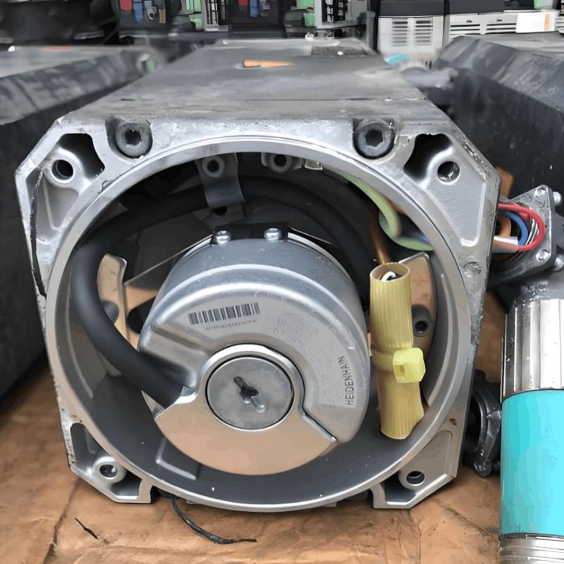
Two Phase AC Servo Motor

Encyclopedia
04/23/2025

Two Phase AC Servo Motor

In a previous article, we've already explored servo motors. In this one, we'll focus on two - phase and three - phase AC servo motors.

The stator of a two - phase AC servo motor is equipped with two distributed windings. These windings are electrically displaced from each other by 90 degrees. One of these windings is called the reference or fixed phase. It is powered by a constant - voltage source, ensuring a stable electrical input. The other winding is known as the control phase. It receives a variable voltage, which allows for flexible control of the motor's operation.

The connection diagram of the two - phase AC servo motor is presented below:

image.png

The control phase of a two - phase AC servo motor is typically powered by a servo amplifier. The rotational speed and torque output of the rotor are regulated by the phase difference between the control voltage and the reference phase voltage. This phase difference acts as a key control parameter; by altering it, specifically by reversing the phase relationship from a leading to a lagging condition or vice versa, the direction of the rotor's rotation can be reversed.

The torque - speed characteristic curve of the two - phase AC servomotor is illustrated in the figure below. This curve provides valuable insights into how the motor's torque varies with different speeds, which is essential for understanding and optimizing its performance in various applications.

image.png

A negative slope in the torque - speed characteristic curve indicates a high rotor resistance. This high resistance endows the motor with positive damping, significantly enhancing its stability during operation. Notably, the curve remains approximately linear across a wide range of control voltages, ensuring consistent performance under varying electrical inputs.

To further optimize the motor's responsiveness to weak control signals, engineers have developed a specialized design known as the Drag Cup Servo motor. By reducing the motor's weight and inertia, this design allows for a more rapid and precise reaction to even the slightest control voltage changes. The figure below showcases the distinctive structure of the Drag Cup Servo motor, highlighting its innovative features that contribute to superior performance.

image.png

Drag Cup Servo Motor

The rotor of the Drag cup servo motor is ingeniously fabricated from a thin - walled cup made of non - magnetic conducting material. Nestled at the core of this conducting cup is a stationary iron core, which plays a pivotal role in closing the magnetic circuit, ensuring efficient magnetic flux linkage. Owing to the rotor's slender structure, its electrical resistance is significantly elevated. This high resistance is not merely a physical property but a key performance enhancer, as it directly gives rise to a remarkably high starting torque. With this enhanced torque, the motor can swiftly accelerate from a standstill and respond with exceptional agility to control signals, making it an ideal choice for applications that demand rapid and precise positioning, such as in high - end robotics and precision manufacturing equipment.

Three - Phase AC Servo Motors

In the realm of high - power servo systems, three - phase induction motors integrated with voltage control mechanisms have emerged as the workhorses for servo applications. By their very nature, three - phase squirrel cage induction motors are complex, highly nonlinear coupled circuit devices, presenting challenges in achieving precise control. However, through the implementation of advanced control strategies like Vector Control, also known as Field Oriented Control, these motors can be transformed into linear, decoupled machines.

This sophisticated control methodology involves the meticulous regulation of the motor's current. It strategically decouples the control of torque and magnetic flux, separating two traditionally intertwined aspects of motor operation. This decoupling is a technological breakthrough, as it empowers the motor to deliver an astonishingly rapid speed response and generate substantial torque instantaneously. Consequently, three - phase AC servo motors controlled via Vector Control are capable of delivering unparalleled performance, meeting the exacting demands of high - power servo applications with unwavering precision and remarkable efficiency. Whether it's in heavy - duty industrial machinery or large - scale automated systems, these motors ensure smooth, accurate, and reliable operation under the most demanding conditions.

Encyclopedia

The Electricity Encyclopedia is dedicated to accelerating the dissemination and application of electricity knowledge and adding impetus to the development and innovation of the electricity industry.

Cost Differences and Performance Comparison of 35kV New Energy Transformers Based on Dry-Type, Mineral Oil, and Vegetable Oil
For users, when purchasing a 35kV new energy transformer, choosing between dry-type, mineral oil-filled, or vegetable oil-filled types involves multiple considerations. These include user habits, maintenance-free performance, safety and fire resistance, volume and weight, among others. However, cost differences are undoubtedly one of the most crucial factors.To illustrate the issue intuitively, this paper selects a three-level energy efficiency dual-winding new energy transformer with a rated ca
Ron
07/26/2025
What is the connection group of a transformer?
Transformer Connection GroupThe connection group of a transformer refers to the phase difference between the primary and secondary voltages or currents. It is determined by the winding directions of the primary and secondary coils, the labeling of their start and end terminals, and the connection mode. Expressed in a clock-like format, there are 12 groups in total, numbered from 0 to 11.The DC method is commonly used to measure the transformer's connection group, mainly to verify whether the con
Vziman
07/26/2025
What is the sequence for powering down the transformer?
The sequence for shutting down a main transformer is as follows: when de-energizing, the load side should be shut down first, followed by the power supply side. For energizing operations, the reverse order applies: the power supply side is energized first, then the load side. This is because: Energizing from the power supply side to the load side makes it easier to identify the fault range and take prompt judgment and handling measures in case of a fault, preventing the fault from spreading or e
Rockwell
07/26/2025
What are the methods for switching operations of station transformers?
Let's take an auxiliary power system with two station transformers as an example. When one station transformer needs to be out of service, there are two operation methods: non-interruptive power supply and instantaneous power interruption. Generally, the method of instantaneous power interruption on the low-voltage side is preferred.The operation method for instantaneous power interruption on the low-voltage side is as follows:Open the 380V power incoming circuit breaker of the corresponding sec
Vziman
07/26/2025
Inquiry
Download
IEE-Business is dedicated to serving the personnel in the global power industry.
Join IEE-Business, not only can you discover power equipment and power knowledge, but also canhnd like - minded friends!