How work operation amplifier (O- Pamp)?

Encyclopedia
11/21/2024

How Does an Operational Amplifier Work?

An operational amplifier (Op-Amp) is a highly integrated electronic component widely used in circuits for signal amplification, filtering, integration, differentiation, and many other applications. Its primary function is to amplify the difference in voltage between its two input terminals. Here is an explanation of how an operational amplifier works and key concepts:

1. Basic Structure

  • An operational amplifier typically has five pins:

  • Non-Inverting Input (V+): Positive input terminal.

  • Inverting Input (V−): Negative input terminal.

  • Output (Vout ): Amplified output signal.

  • Positive Supply (Vcc ): Positive power supply voltage.

  • Negative Supply (Vee ): Negative power supply voltage.

2. Working Principle

Assumptions for an Ideal Operational Amplifier

  • Infinite Gain: Ideally, the gain A of the op-amp is infinite.

  • Infinite Input Impedance: The input impedance Rin  is infinite, meaning the input current is almost zero.

  • Zero Output Impedance: The output impedance Rout is zero, meaning the output current can be arbitrarily large without affecting the output voltage.

  • Infinite Bandwidth: Ideally, the op-amp can operate at all frequencies without any limitations.

Characteristics of a Real Operational Amplifier

  • Finite Gain: In practice, the gain A of the op-amp is finite, typically ranging from Ten to the fifth power to Ten to the sixth power.

  • Finite Input Impedance: The actual input impedance is not infinite but is very high (megohms level).

  • Non-Zero Output Impedance: The actual output impedance is not zero but is very low.

  • Finite Bandwidth: The actual bandwidth of the op-amp is limited, typically ranging from hundreds of kilohertz to megahertz.

3. Basic Operating Modes

Open-Loop Configuration

Open-Loop Gain: In open-loop configuration, the op-amp's gain A directly amplifies the differential input voltage

e98bade167c6a425814146736aef9031.jpeg

Saturation: Due to the high gain A, even a small input voltage difference can cause the output voltage to reach the limits of the power supply voltages (i.e., Vcc or Vee ).

Closed-Loop Configuration

Negative Feedback: By introducing negative feedback, the gain of the op-amp can be controlled to operate within a reasonable range.

Negative Feedback Circuit: Common negative feedback circuits include inverting amplifiers, non-inverting amplifiers, and differential amplifiers.

Virtual Short and Virtual Open: In negative feedback circuits, the voltages at the two input terminals of the op-amp are almost equal (virtual short), and the input current is almost zero (virtual open).

4. Common Application Circuits

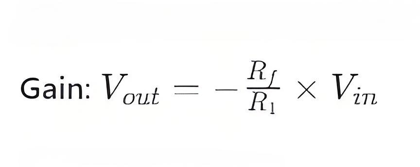
Inverting Amplifier

Circuit Structure: The input signal is fed through a resistor 

Circuit Structure: The input signal is fed through a resistor R1 to the inverting input V − , and a feedback resistor Rf connects the output 

Vout  to the inverting input V- .

53129bc1db8137cf1060b0103f981ef0.jpeg

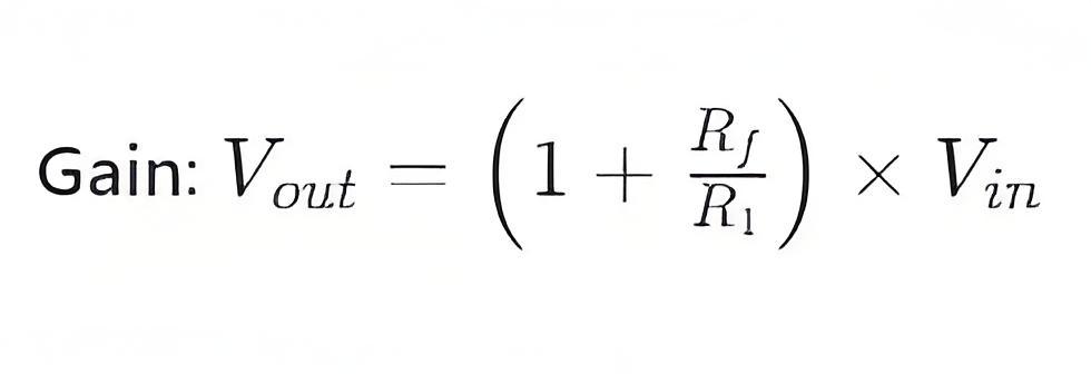
Non-Inverting Amplifier

Circuit Structure: The input signal is fed through a resistor R1  to the non-inverting input V + , and a feedback resistor Rf connects the output Vout  to the inverting input V− .

933b48e586a06a1d1140efaf3129d811.jpeg

Differential Amplifier

Circuit Structure: Two input signals are applied to the non-inverting input V+  and the inverting input V− , and a feedback resistor Rf connects the output V out  to the inverting input V − .

1157b5d8b83b78f7cfce016d52bbd0ee.jpeg

5. Summary

An operational amplifier works by amplifying the difference in voltage between its two input terminals, with the core functionality relying on high gain and negative feedback mechanisms. By using different circuit configurations, op-amps can perform various functions such as amplification, filtering, integration, and differentiation. Understanding the working principles and common application circuits of op-amps is essential for designing and troubleshooting various electronic systems.

Encyclopedia

The Electricity Encyclopedia is dedicated to accelerating the dissemination and application of electricity knowledge and adding impetus to the development and innovation of the electricity industry.

Cost Differences and Performance Comparison of 35kV New Energy Transformers Based on Dry-Type, Mineral Oil, and Vegetable Oil
For users, when purchasing a 35kV new energy transformer, choosing between dry-type, mineral oil-filled, or vegetable oil-filled types involves multiple considerations. These include user habits, maintenance-free performance, safety and fire resistance, volume and weight, among others. However, cost differences are undoubtedly one of the most crucial factors.To illustrate the issue intuitively, this paper selects a three-level energy efficiency dual-winding new energy transformer with a rated ca
Ron
07/26/2025
What is the connection group of a transformer?
Transformer Connection GroupThe connection group of a transformer refers to the phase difference between the primary and secondary voltages or currents. It is determined by the winding directions of the primary and secondary coils, the labeling of their start and end terminals, and the connection mode. Expressed in a clock-like format, there are 12 groups in total, numbered from 0 to 11.The DC method is commonly used to measure the transformer's connection group, mainly to verify whether the con
Vziman
07/26/2025
What is the sequence for powering down the transformer?
The sequence for shutting down a main transformer is as follows: when de-energizing, the load side should be shut down first, followed by the power supply side. For energizing operations, the reverse order applies: the power supply side is energized first, then the load side. This is because: Energizing from the power supply side to the load side makes it easier to identify the fault range and take prompt judgment and handling measures in case of a fault, preventing the fault from spreading or e
Rockwell
07/26/2025
What are the methods for switching operations of station transformers?
Let's take an auxiliary power system with two station transformers as an example. When one station transformer needs to be out of service, there are two operation methods: non-interruptive power supply and instantaneous power interruption. Generally, the method of instantaneous power interruption on the low-voltage side is preferred.The operation method for instantaneous power interruption on the low-voltage side is as follows:Open the 380V power incoming circuit breaker of the corresponding sec
Vziman
07/26/2025
Inquiry
Download
IEE-Business is dedicated to serving the personnel in the global power industry.
Join IEE-Business, not only can you discover power equipment and power knowledge, but also canhnd like - minded friends!