Basic Principles and Types of Inverters
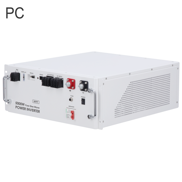
An inverter is a power electronic device that converts direct current (DC) into alternating current (AC). It is widely used in renewable energy systems, uninterruptible power supplies (UPS), electric vehicles, and other applications. Depending on the specific application and technical requirements, inverters can operate based on different principles and come in various types. Below are some common types of inverters and their working principles:
1. Single-Phase Inverter
Principle: A single-phase inverter converts DC power to single-phase AC power. It is typically used for household electricity or small equipment. The output waveform of a single-phase inverter can be a square wave, modified sine wave, or pure sine wave.
Square Wave Inverter: The output waveform is a simple square wave, suitable for basic loads but generates significant harmonic interference, making it unsuitable for sensitive devices.
Modified Sine Wave Inverter: The output waveform is between a square wave and a sine wave, with lower harmonic content, suitable for most household appliances.
Pure Sine Wave Inverter: The output waveform closely resembles an ideal sine wave, with minimal harmonic content, suitable for devices requiring high-quality power, such as computers and medical equipment.
Application: Home solar systems, small UPS units, portable power sources, etc.
2. Three-Phase Inverter
Principle: A three-phase inverter converts DC power to three-phase AC power. It is commonly used in industrial motor drives, large photovoltaic (PV) systems, and wind power generation. The output waveform of a three-phase inverter is also a sine wave, providing more stable power for high-power devices.
Application: Industrial motor drives, large PV power plants, wind power generation, electric vehicle drive systems, etc.
3. Voltage Source Inverter (VSI)
Principle: A voltage source inverter (VSI) connects to a fixed DC voltage source (such as a battery or rectifier) at its input and uses switching devices (like IGBTs or MOSFETs) to control the output AC voltage. VSI regulates the output voltage amplitude and frequency by adjusting the switching frequency and duty cycle.
Characteristics: Provides stable output voltage, suitable for applications requiring high voltage quality. The output current depends on the load characteristics and may exhibit significant fluctuations.
Application: Home inverters, UPS systems, electric vehicles, etc.
4. Current Source Inverter (CSI)
Principle: A current source inverter (CSI) connects to a fixed DC current source at its input and controls the output AC current using switching devices. CSI regulates the output current amplitude and frequency by adjusting the switching frequency and duty cycle.
Characteristics: Provides stable output current, suitable for applications requiring precise current control. The output voltage depends on the load characteristics and may exhibit significant fluctuations.
Application: Industrial motor drives, induction heating, etc.
5. Pulse Width Modulation Inverter (PWM Inverter)
Principle: A PWM inverter controls the output voltage amplitude and frequency by adjusting the conduction time (i.e., pulse width) of the switching devices. PWM technology can produce an output waveform that closely resembles a sine wave, reducing harmonic distortion and improving power quality.
Characteristics: High-quality output waveform, high efficiency, suitable for applications requiring high power quality. PWM inverters can achieve different AC frequencies by varying the switching frequency.
Application: Home inverters, industrial motor drives, UPS systems, PV inverters, etc.
6. Multilevel Inverter
Principle: A multilevel inverter generates a multi-level output voltage waveform by combining multiple DC sources or multiple switching devices. Compared to traditional two-level inverters, multilevel inverters produce an output waveform that is much closer to a sine wave, with lower harmonic content and reduced switching losses.
Characteristics: Extremely high-quality output waveform, suitable for high-power, high-voltage applications. Multilevel inverters can reduce the need for filters, lowering system complexity and cost.
Application: High-voltage direct current (HVDC) transmission, large industrial motor drives, wind power generation, etc.
7. Isolated Inverter
Principle: An isolated inverter includes a transformer between the DC side and the AC side, providing electrical isolation. This design prevents faults on the DC side from affecting the AC side and enhances system safety.
Characteristics: Excellent electrical isolation, suitable for applications requiring safe isolation. Isolated inverters can also use transformers to step up or step down the voltage, adapting to different load requirements.
Application: Medical equipment, industrial control systems, distributed generation systems, etc.
8. Non-Isolated Inverter
Principle: A non-isolated inverter does not have a built-in transformer, and the DC side is directly connected to the AC side. This design simplifies the circuit structure, reduces cost and size, but lacks electrical isolation, which may affect system safety.
Characteristics: Simple structure, low cost, high efficiency, unsuitable for applications requiring electrical isolation.
Application: Home solar systems, small UPS units, etc.
9. Bidirectional Inverter
Principle: A bidirectional inverter can convert DC to AC and also convert AC back to DC. This allows for bidirectional energy flow, enabling the inverter to both discharge energy from a storage system (like a battery) and feed excess energy back into the grid or charge the storage system.
Characteristics: Supports bidirectional energy flow, suitable for energy storage systems, electric vehicle charging stations, etc.
Application: Energy storage systems, electric vehicle charging, microgrids, etc.
10. Grid-Tied Inverter
Principle: A grid-tied inverter converts DC power (e.g., from solar panels) into AC power that is synchronized with the grid and feeds it into the grid. Grid-tied inverters must have synchronization capabilities to ensure that the output AC matches the grid's voltage, frequency, and phase.
Characteristics: Can sell excess energy back to the grid, enabling efficient energy utilization. Grid-tied inverters typically include anti-islanding protection to prevent operation during grid faults.
Application: Grid-connected PV systems, wind power generation, etc.
11. Off-Grid Inverter
Principle: An off-grid inverter operates independently of the grid and is typically used with a storage system (like a battery). It converts DC power into AC power for local loads. Off-grid inverters do not need to synchronize with the grid but must provide stable voltage and frequency to ensure high-quality AC output.
Characteristics: Independent operation, suitable for remote areas or locations without grid access. Off-grid inverters often include battery management systems to ensure proper operation of the storage system.
Application: Power supply in remote areas, emergency power, independent power generation systems, etc.
Summary
Inverters operate based on various principles and come in different types depending on the specific application and technical requirements. Single-phase and three-phase inverters are suited for different load types; voltage source and current source inverters differ based on their output characteristics; PWM and multilevel technologies improve output waveform quality; isolated and non-isolated inverters offer different levels of safety; bidirectional inverters support bidirectional energy flow; grid-tied and off-grid inverters are designed for grid-connected and independent operation, respectively.


