What is a Servo Motor Controller ?

Encyclopedia
08/23/2024


What is a  Servo Motor Controller ?


Servo Motor Controller Definition


A servo motor controller (or servo motor driver) is defined as a circuit used to control the position of a servo motor.


Servo Motor Driver Circuit


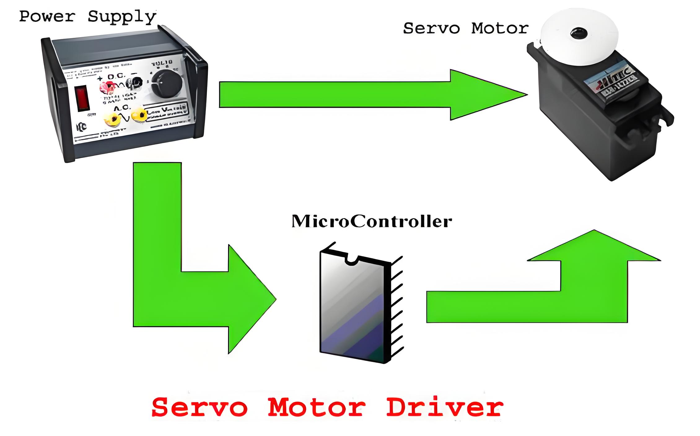
The servo motor driver circuit includes a micro-controller, power supply, potentiometer, and connectors, ensuring precise motor control.


Micro-controller Role


The micro-controller generates PWM pulses at specific intervals to control the servo motor’s position accurately.


Power Supply


The power supply design for a servo motor controller depends on the number of connected motors. Servo motors typically use a 4.8V to 6V supply, with 5V being standard. Exceeding the supply voltage can damage the motor. The current draw varies with the torque and is lower in idle mode and higher when running. The maximum current draw, known as stall current, can reach up to 1A for some motors.


For single motor control, use a voltage regulator like LM317 with a heat sink. For multiple motors, a high-quality power supply with a higher current rating is necessary. An SMPS (Switched Mode Power Supply) is a good choice.


Block Diagram below-showing interconnections in a Servo Motor Driver


070200dd6b74d3a766ea99ada66c86b6.jpeg


Controlling Servo Motor


The servo motor has three terminals.


  • Position signal(PWM Pulses)

  • Vcc (From Power Supply)

  • Ground


bd99e48d2428dc57f8d8cce455130a89.jpeg


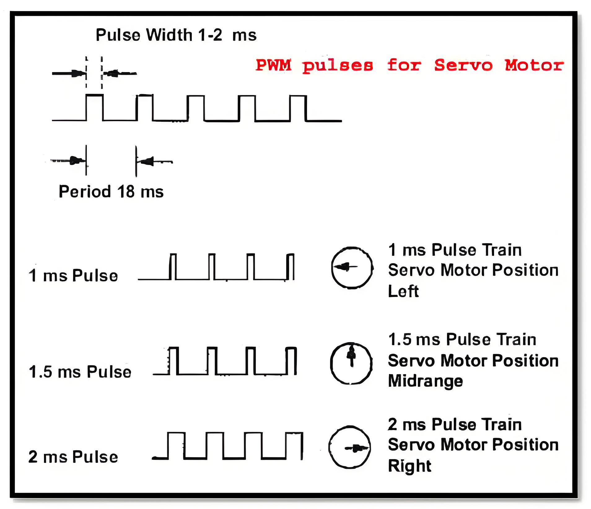
The servo motor’s angular position is controlled by applying PWM pulses of specific widths. The pulse duration ranges from about 0.5ms for 0-degree rotation to 2.2ms for 180-degree rotation. The pulses should be given at frequencies around 50Hz to 60Hz.


In order to generate the PWM (Pulse Width Modulation) waveform, as shown in the figure below, one can use either the internal PWM module of the micro-controller or the timers can be used. Using the PWM block is more flexible as most micro-controller families design, and this PWM block better suits the needs of applications such as a servo motor. For different widths of PWM pulses, we need to program the internal registers accordingly.


Now, we also need to tell the microcontroller how much it has to rotate. For this purpose, we can use a simple potentiometer and use an ADC to get the rotation angle or for more complex applications an accelerometer can be used.


3b0074e2-cb49-45d2-9bd2-24f43a18e605.jpg


Program Algorithm


Let us design the Program to control a single servo and the position input is given via the potentiometer connected to a pin of controller.


  • Nitialize the port pins for input/output.


  • Read the ADC for desired servo position.


  • Program the PWM registers for the desired value.


  • As soon as you trigger the PWM module, the selected PWM channel pin goes high (logic 1) and after the required width is reached, it will again go low (logic 0). So after triggering the PWM, you must start a timer with a delay of about 19 ms and wait until the timer overflowsGo to step 2


There are various modes of PWM available which you can use depending on the microcontroller you choose. Some degree of optimization should be done in the code to control the servo.


If you plan to use more than one servo than you will require as many PWM channels. Each servo can be given the PWM signal sequentially. But you must take care that the pulse repetition rate for each servo is maintained. Otherwise the servo will run out of synchronization.


Encyclopedia

The Electricity Encyclopedia is dedicated to accelerating the dissemination and application of electricity knowledge and adding impetus to the development and innovation of the electricity industry.

Cost Differences and Performance Comparison of 35kV New Energy Transformers Based on Dry-Type, Mineral Oil, and Vegetable Oil
For users, when purchasing a 35kV new energy transformer, choosing between dry-type, mineral oil-filled, or vegetable oil-filled types involves multiple considerations. These include user habits, maintenance-free performance, safety and fire resistance, volume and weight, among others. However, cost differences are undoubtedly one of the most crucial factors.To illustrate the issue intuitively, this paper selects a three-level energy efficiency dual-winding new energy transformer with a rated ca
Ron
07/26/2025
What is the connection group of a transformer?
Transformer Connection GroupThe connection group of a transformer refers to the phase difference between the primary and secondary voltages or currents. It is determined by the winding directions of the primary and secondary coils, the labeling of their start and end terminals, and the connection mode. Expressed in a clock-like format, there are 12 groups in total, numbered from 0 to 11.The DC method is commonly used to measure the transformer's connection group, mainly to verify whether the con
Vziman
07/26/2025
What is the sequence for powering down the transformer?
The sequence for shutting down a main transformer is as follows: when de-energizing, the load side should be shut down first, followed by the power supply side. For energizing operations, the reverse order applies: the power supply side is energized first, then the load side. This is because: Energizing from the power supply side to the load side makes it easier to identify the fault range and take prompt judgment and handling measures in case of a fault, preventing the fault from spreading or e
Rockwell
07/26/2025
What are the methods for switching operations of station transformers?
Let's take an auxiliary power system with two station transformers as an example. When one station transformer needs to be out of service, there are two operation methods: non-interruptive power supply and instantaneous power interruption. Generally, the method of instantaneous power interruption on the low-voltage side is preferred.The operation method for instantaneous power interruption on the low-voltage side is as follows:Open the 380V power incoming circuit breaker of the corresponding sec
Vziman
07/26/2025
Inquiry
Download
IEE-Business is dedicated to serving the personnel in the global power industry.
Join IEE-Business, not only can you discover power equipment and power knowledge, but also canhnd like - minded friends!