
Definition: An energy meter is a device used to measure the electrical energy consumed by an electrical load. Electrical energy refers to the total power consumed and utilized by a load over a specific period of time. Energy meters are used in domestic and industrial AC circuits to measure power consumption. They are relatively inexpensive and accurate.
Construction of an Energy Meter
The construction of a single - phase energy meter is shown in the figure below.
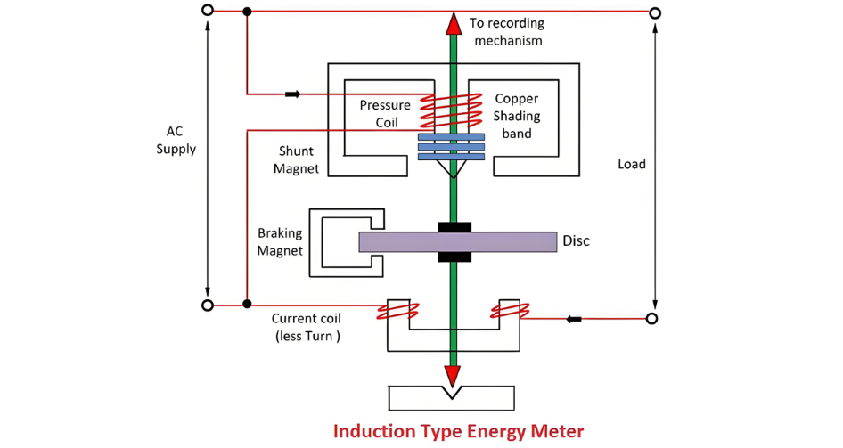
The energy meter consists of four main components, namely:
A detailed explanation of each component is provided below.
Driving System
The electromagnet serves as the core component of the driving system. It functions as a temporary magnet, activated by the electric current passing through its coil. The core of this electromagnet is constructed from silicon steel laminations.
Within the driving system, there are two electromagnets. The upper one is referred to as the shunt electromagnet, while the lower one is known as the series electromagnet.
The central limb of the magnet is equipped with a copper band, which is adjustable. The key role of this copper band is to align the magnetic flux generated by the shunt magnet in a manner that makes it perfectly perpendicular to the supplied voltage.
Moving System
The moving system features an aluminium disc mounted on an alloy shaft. This disc is positioned within the air gap between the two electromagnets. As the magnetic field changes, eddy currents are induced in the disc. These eddy currents interact with the magnetic flux, generating a deflecting torque.
When electrical devices draw power, the aluminium disc begins to rotate. After a certain number of rotations, the disc indicates the amount of electrical energy consumed by the load. The number of rotations is counted over a specific time interval, and the disc measures power consumption in kilowatt - hours.
Braking System
A permanent magnet is employed to slow down the rotation of the aluminium disc. As the disc rotates, it induces eddy currents. These eddy currents interact with the magnetic flux of the permanent magnet, creating a braking torque.
This braking torque opposes the disc’s motion, reducing its rotational speed. The permanent magnet is adjustable; by repositioning it radially, the braking torque can be modified.
Registration (Counting Mechanism)
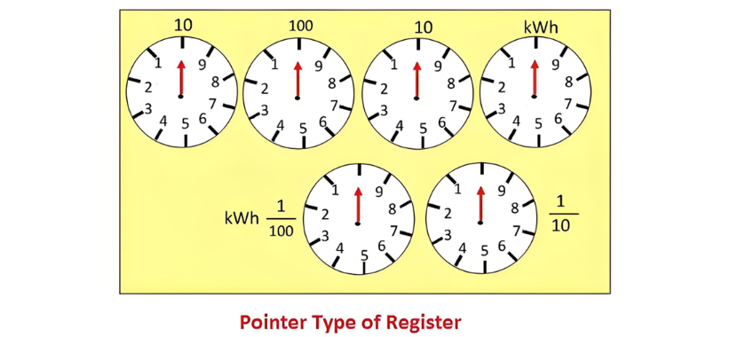
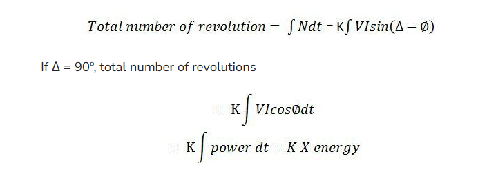
The primary function of the registration, or counting mechanism, is to record the number of rotations of the aluminium disc. The disc’s rotation is directly proportional to the electrical energy consumed by the load, measured in kilowatt - hours.
The disc’s rotation is transmitted to the pointers of various dials to record different readings. The energy consumption in kilowatt - hours is calculated by multiplying the number of disc rotations by the meter constant. The dial configuration is shown in the figure below.
Working Principle of the Energy Meter
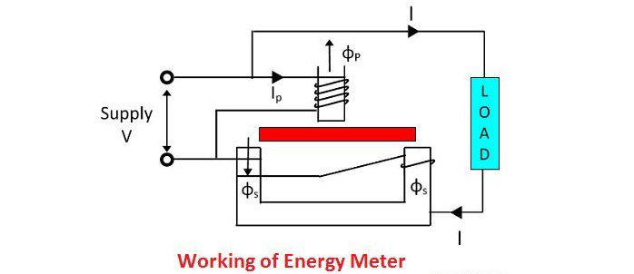
An energy meter features an aluminium disc, whose rotation is used to determine the power consumption of the load. This disc is positioned in the air gap between the series electromagnet and the shunt electromagnet. The shunt magnet is equipped with a pressure coil, while the series magnet has a current coil.
The pressure coil generates a magnetic field due to the supply voltage, and the current coil produces a magnetic field as a result of the load current passing through it.
The magnetic field induced by the voltage (pressure) coil lags the magnetic field of the current coil by 90°. This phase difference induces eddy currents in the aluminium disc. The interaction between these eddy currents and the combined magnetic fields generates a torque, which exerts a rotational force on the disc. Consequently, the disc starts to rotate.
The rotational force acting on the disc is proportional to the current through the current coil and the voltage across the pressure coil. The permanent magnet in the braking system regulates the disc’s rotation. It opposes the disc’s movement, ensuring the rotational speed aligns with the actual power consumption. A cyclometer (registering mechanism) then counts the number of rotations of the disc to quantify energy usage.
Theory of the Energy Meter
The pressure coil has a relatively large number of turns, making it highly inductive. The magnetic circuit of the pressure coil has a very low reluctance path, thanks to the small air - gap length in its magnetic structure. The current Ip flowing through the pressure coil, driven by the supply voltage, lags the supply voltage by approximately 90° due to the coil’s high inductance.
The current Ip generates two magnetic fluxes, Φp, which is further split into Φp1 and Φp2. A major portion of the flux Φp1 passes through the side gap due to its low reluctance. The flux Φp2 travels through the disc and induces a driving torque that causes the aluminium disc to rotate.
The flux Φp is proportional to the applied voltage and lags behind the voltage by an angle of 90°. Since this flux is alternating, it induces an eddy current Iep in the disc.
The load current flowing through the current coil induces a flux Φs. This flux generates an eddy current Ies in the disc. The eddy current Ies interacts with the flux Φp, and the eddy current Iep interacts with Φs, resulting in another torque. These two torques act in opposite directions, and the net torque is the difference between them.
The phasor diagram of the energy meter is shown in the figure below.

Let
V – applied voltage
I – load current
∅ – the phase angle of load current
Ip – pressure angle of load
Δ – the phase angle between supply voltage and pressure coil flux
f – frequency
Z – impedance of eddy current
∝ – the phase angle of eddy current paths
Eep – eddy current induced by flux
Iep – eddy current due to flux
Eev – eddy current due to flux
Ies – eddy current due to flux
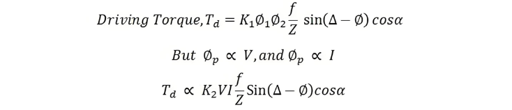
The net driving torque of the dis is expressed as

where K1 – constant
Φ1 and Φ2 are the phase angle between the fluxes. For energy meter, we take Φp and Φs.
β – phase angle between fluxes Φp and Φp = (Δ – Φ), therefore
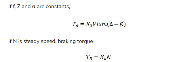
At steady state, the speed of the driving torque is equal to the braking torque.
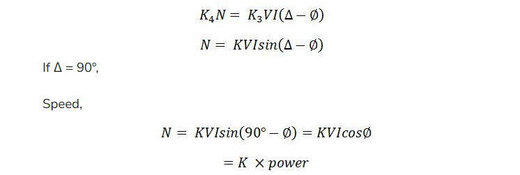
The speed of the rotation is directly proportional to the power.
The three phase energy meter is used for measuring the large power consumption.


