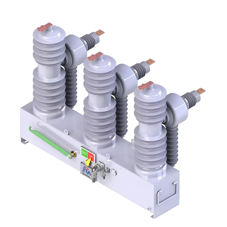
15kV/1250A MV outdoor vacuum Auto Circuit recloser
$5000.00
Model
| Brand | ROCKWILL |
| Model NO. | 15kV/1250A MV outdoor vacuum Auto Circuit recloser |
| Rated voltage | 15kV |
| Rated normal current | 400A |
| Rated short circuit breaking current | 12.5kA |
| Power frequency withstand voltage | 36kV/min |
| Rated lightning impulse voltage | 110kV |
| manual closing | No |
| Mechanical lock | |
| Series | RCW |
Description:
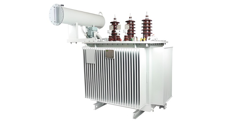
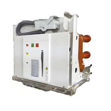
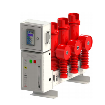
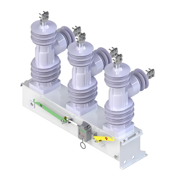
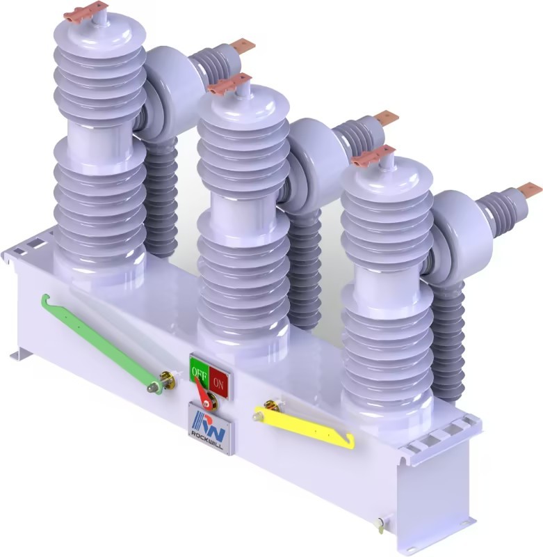
The RCW series automatic circuit reclosers can use on overheaddistribution lines as well as distribution substation applications for all voltage classes 11kV up to 38kV at 50/60Hz power system. and it’s rated current can reach 1250A.The RCW series automatic circuit reclosers integrates the functions of control, protection, measurement, communication, fault detection, on-line monitoring of closing or opening.The RCW series vacuum recloser is mainly combined with integration terminal, current transformer, permanent magnetic actuator and it’srecloser controller.
Features:
Optional grades available in rated current range.
With optional relay protection and logic for user selection.
With optional communication protocols and I/O ports for users to choose.
PC software for controller testing, setup, programming, updates.
Parameters


Environmental requirement:

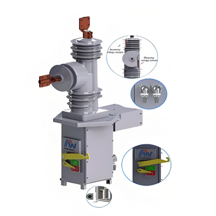
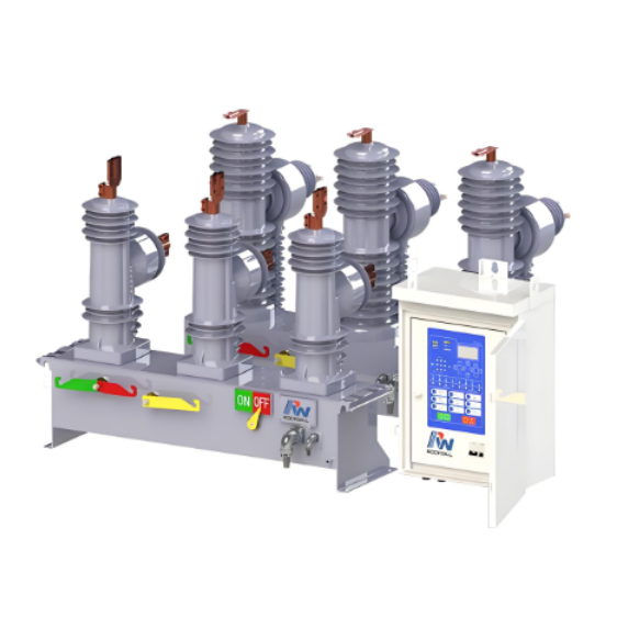
Product show:


What is the vacuum arc extinguishing fault of outdoor vacuum recloser and its solution?
Decreased Vacuum Level: This is a common issue with vacuum arc quenching chambers. The vacuum arc quenching chamber relies on a high-vacuum environment to extinguish arcs. If the vacuum level decreases, its insulation performance and arc-quenching ability will significantly deteriorate. The causes of decreased vacuum levels can include poor sealing, such as aging or damaged sealing materials, or tiny leaks present during the manufacturing process. When the vacuum level drops to a certain extent, incomplete arc extinction may occur during current interruption, leading to arc reignition and subsequent line faults.
Contact Wear: During frequent opening and closing operations, the contacts of the vacuum arc quenching chamber can wear down due to arc erosion. Contact wear increases contact resistance, which can lead to severe heating of the contacts when normal current passes through, affecting the normal operation of the equipment. Additionally, during fault current interruption, the contacts may not withstand the high current, resulting in contact welding or failure to interrupt the current.
Detect Vacuum Level: Use specialized vacuum level detection instruments, such as vacuum level testers, to regularly check the vacuum level of the vacuum arc quenching chamber. Once the vacuum level is found to be below the specified value, the vacuum arc quenching chamber should be replaced promptly.
Replace Seals: If you suspect that poor sealing is causing the decrease in vacuum level, inspect and replace the seals. When replacing seals, ensure that you use high-quality, compatible sealing materials and follow the correct installation procedures to prevent further leakage.
Regular Inspection: Regularly inspect the wear condition of the contacts through observation windows or by disassembling the device. Based on the degree of wear, if the wear exceeds the specified limit, the contacts should be replaced promptly.
Optimize Operating Parameters: Analyze the causes of contact wear, such as whether it is due to frequent operations or excessive operating current. If the issue is frequent operation, consider optimizing the recloser's reclosing strategy to reduce unnecessary opening and closing operations. If the issue is excessive operating current, check the line load conditions, adjust the protection settings, and avoid subjecting the contacts to excessive current impacts.