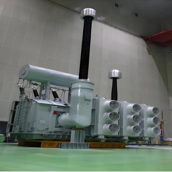
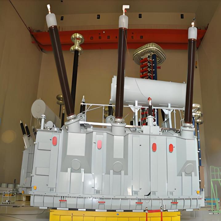
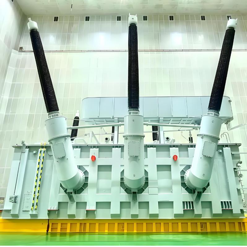
735kV 750kV 765kV Single-phase Oil-Immersed Autotransformer with Three Windings and No Excitation
Key attributes
| Brand | ROCKWILL |
| Model NO. | 735kV 750kV 765kV Single-phase Oil-Immersed Autotransformer with Three Windings and No Excitation |
| Rated voltage | 750kV |
| Rated frequency | 50/60Hz |
| Rated capacity | 500kVA |
| Series | ODFPS |
Product descriptions from the supplier
Product Description:
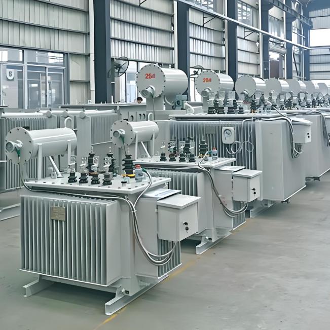
As a pioneer in China's power transformer industry, we have specialized in the R&D and manufacturing of power transformer equipment for decades, and established industry standards with core technologies.
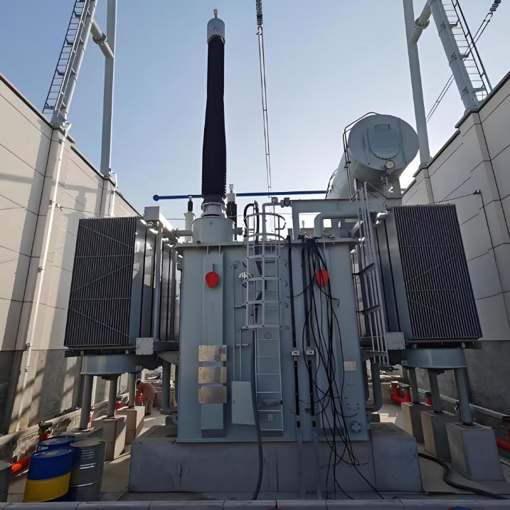
The 750kV Single-phase Oil-Immersed Autotransformer with Three Windings and No Excitation is a critical component designed for the highest tiers of power transmission systems. Its robust oil-immersed cooling technology ensures stable thermal performance and long-term reliability under heavy loads. The unique three-winding configuration provides exceptional operational flexibility, enabling efficient power transfer and system interconnection. As a "no excitation" design, it offers superior reliability and simplified maintenance by eliminating the need for on-load tap-changing mechanisms, making it an ideal and dependable solution for ultra-high voltage (UHV) grid applications that demand unwavering performance.
This power transformer is fully compliant with international standards including IEC 60076-1, IEEE C57.12.00, ANSI C57.12.90, AS/NZS 60076.5 and EN 61558-1. It meets quality requirements and is widely adaptable to the operational needs of power grids in multiple overseas regions.
Product Characteristics:
Optimized Structural Design: Utilizes advanced computational analysis of electrical, magnetic, mechanical, and thermal behavior to ensure robust and reliable construction.
Superior Electrical Performance: Complies with IEC standards while offering customized solutions, with partial discharge levels significantly lower than IEC 60076-3 limits.
Enhanced Operational Reliability: Multi-physics field analysis optimizes insulation, amp-turns balance, and cooling, delivering strong resilience to overvoltage and short-circuit events while eliminating risks of local overheating.
Premium Component Selection: Provides an exceptional user experience with a clean appearance, leak-free construction, and maintenance-free operation—no core disassembly required.
Technical Parameters
The voltage classes of some of these Power Transformer include 6kV, 6.3kV, 6.6kV, 6.9kV, 7.2kV, 10kV, 10.5kV, 11kV, 11.5kV, 12kV, 13.2kV, 13.8kV, 14.5kV, 14.4kV, 15kV, 15.5kV, 15.6kV, 17.5kV, 20kV, 21.9kV, 22kV, 24kV, 30kV, 33kV, 33.5kV, 34.5kV, 35kV, 36kV, 38kV, 38.5kV, 40.5kV, 44kV, 45kV, 46kV, 66kV 69kV.72.5kV 88kV 110kV 115kV 123kV 125kV 126kV 132kV 138kV 145kV 150kV 154kV 161kV 170kV 220kV 225kV 230kV 245kV 275kV 330kV 345kV 363kV 380kV 400kV 500kV Power transformers of voltage ,and aboveand customization is available.
Among these, some autotransformers cover non-standard voltage levels including 121kV, 132kV, 138kV, 200kV, 225kV, 230kV, 245kV, 275kV, 330kV, 345kV, 400kV and 756kV, We also provide customization services.
Rated capacity (kVA) |
334 |
500 |
500 |
700 |
|
Voltage combination and tapping range |
HV (kV) |
765/√3 |
|||
Tapping range(kV) |
230/√3±2×2.5% |
345/√3±2×2.5% |
|||
LV (kV) |
63 |
||||
Vector group |
La0I0 |
||||
No-load loss(kW) |
95 |
110 |
125 |
130 |
|
On-load loss(kW) |
570 |
860 |
860 |
1225 |
|
No-load current (%) |
0.15 |
0.15 |
0.15 |
0.15 |
|
Short-circuit impedance (%) |
HV-MV14 HV-LV50 MV-LV33 |
HV ~MV 19 ~ 22 HV-LV46 MV-LV 23~24 |
HV-MV14 HV-LV50 MV-LV33 |
HV-MV18 HV-LV58 MV-LV36 |
|
Capacity assignment (MVA) |
334/334/100 |
500/500/150 |
500/500/150 |
700/700/233 |
|
Note: Transformers with various special parameters and performance can be manufactured according to customer requirements.
Normal Service Conditions
(1) Altitude: ≤1000m;
(2) Ambient temperature:Maximum temperature: +40℃;Maximum monthly average temperature: +30℃;Maximum yearly average temperature: +20℃;Minimum temperature: -25℃.
(3) Power supply: approximate sinusoidal wave, three-phase symmetrical approximately
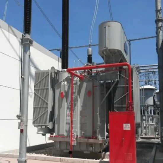
(4) Installation site: indoor or outdoor, without the obvious contamination.Note: The transformer used in special conditions should be specified when ordered.
Introduction to Structure and Performance:
Core:
Adopting highest quality, non-aging, cold-rolled, grain-oriented, and high permeability silicon steel lamination silicon steel sheets.
Processed on the GEORG length-cutting line from Germany.
Fully mitred joint, step lapping and polyester tape binding structure making the transformer with low no-load losses and low noise level.
Placing vibration isolation pads between the body and the tank to reduce vibration that transmits to the tank.
Winding:
Winded by high-quality oxygen free copper with lower resistivity.
Processed and manufactured on horizontal winding machines and large CNC vertical winding machines from both radial and axial directions.
Reasonable transposition applied between paralleling wires, magnetic shielding used for guiding flux leakage when necessary to reduce the stray losses of the transformer.
Reasonable design of insulation structure improving the ability of withstanding overvoltage.
Optimizing the ampere turns distribution of the winding, increasing the radial support and axial compression of the winding, using the pre-densification of spacers, constant pressure drying, to resist the impulse current.
Tank:
Bell type or cover bolted type tank.
Carbon dioxide shielded welding process.
High-quality gaskets and the limit groove.
Strict leak detection test procedures.
Others:
Cold-weld connection technology leads to improve the cleanliness of active part.
The vacuum disassembly and the vacuum filling technology measures reduce the partial discharge level effectively and enhance the transformer operating reliability.
The structure of "Six Direction Positioning" between the active part and the tank assures that the transformer has a strong ability of anti-transportation impact or anti-earthquake.
Surface treatment and coating, fine processing to tank surface, 7 steps such as acid-washing and phosphating, etc. special anti-fouling paint, ensuring not falling off or rusting away.
The oil-immersed design uses insulating oil for two key functions: first, it provides excellent electrical insulation between windings and components; second, it acts as a cooling medium, dissipating heat generated during operation to ensure the transformer works within a safe temperature range, thus extending its service life.
"No excitation" means the transformer can only adjust voltage when it is completely disconnected from the power grid (no load current). This design simplifies the structure, enhances reliability, and is suitable for scenarios where voltage regulation frequency is low and stable grid operation is prioritized.

Related Products
-
6 kV 6.6 kV 7.2 kV 10kV High Voltage H61 H59 Distribution Transformer (Oil immersed)
-
Durable H61 H59 5.5 kV 13.2kV 15kV 33kV Power Distribution Transformer for Sale
-
33kV 34.5kV 35kV 36kV Three-phase Oil-immersed Power Distribution Transformer Original Manufacturer

-
245kV 275kV 400kV 330kV Three-Phase Three-Winding On-Load Tap-Changing Autotransformer
-
800kV 1000kV Single-phase Autotransformer with Three Windings and No Excitation manufacturer
-
500kV 550kV Single-phase Oil-Immersed Air-Cooled Autotransformer with Three Windings and No Excitation
-
34.5kV 35kV 38.5kV 45kV On-Load / Off-Circuit Tap-Changing Oil-Immersed Power Transformer
Related Knowledges
-
 Impact of DC Bias in Transformers at Renewable Energy Stations Near UHVDC Grounding ElectrodesImpact of DC Bias in Transformers at Renewable Energy Stations Near UHVDC Grounding ElectrodesWhen the grounding electrode of an Ultra-High-Voltage Direct Current (UHVDC) transmission system is located close to a renewable energy power station, the return current flowing through the earth can cause a rise in ground potential around the electrode area. This ground potential rise leads to a shift in the neutral-point potential of nearby power transformers, inducing DC bias (or DC offset) in their01/15/2026
 -
 HECI GCB for Generators – Fast SF6 Circuit Breaker1.Definition and Function1.1 Role of the Generator Circuit BreakerThe Generator Circuit Breaker (GCB) is a controllable disconnect point located between the generator and the step-up transformer, serving as an interface between the generator and the power grid. Its primary functions include isolating generator-side faults and enabling operational control during generator synchronization and grid connection. The operating principle of a GCB is not significantly different from that of a standard c01/06/2026
 -
 Distribution Equipment Transformer Testing, Inspection, and Maintenance1.Transformer Maintenance and Inspection Open the low-voltage (LV) circuit breaker of the transformer under maintenance, remove the control power fuse, and hang a “Do Not Close” warning sign on the switch handle. Open the high-voltage (HV) circuit breaker of the transformer under maintenance, close the grounding switch, fully discharge the transformer, lock the HV switchgear, and hang a “Do Not Close” warning sign on the switch handle. For dry-type transformer maintenance: first clean the porcel12/25/2025
 -
 How to Test Insulation Resistance of Distribution TransformersIn practical work, insulation resistance of distribution transformers is generally measured twice: the insulation resistance between thehigh-voltage (HV) windingand thelow-voltage (LV) winding plus the transformer tank, and the insulation resistance between theLV windingand theHV winding plus the transformer tank.If both measurements yield acceptable values, it indicates that the insulation among the HV winding, LV winding, and transformer tank is qualified. If either measurement fails, pairwise12/25/2025
 -
 Design Principles for Pole-Mounted Distribution TransformersDesign Principles for Pole-Mounted Distribution Transformers(1) Location and Layout PrinciplesPole-mounted transformer platforms should be located near the load center or close to critical loads, following the principle of “small capacity, multiple locations” to facilitate equipment replacement and maintenance. For residential power supply, three-phase transformers may be installed nearby based on current demand and future growth projections.(2) Capacity Selection for Three-Phase Pole-Mounted Tr12/25/2025
 -
 Transformer Noise Control Solutions for Different Installations1.Noise Mitigation for Ground-Level Independent Transformer RoomsMitigation Strategy:First, conduct a power-off inspection and maintenance of the transformer, including replacing aged insulating oil, checking and tightening all fasteners, and cleaning dust from the unit.Second, reinforce the transformer foundation or install vibration isolation devices—such as rubber pads or spring isolators—selected based on the severity of vibration.Finally, strengthen sound insulation at weak points of the ro12/25/2025
Related Solutions
-
 Intelligent Operation Solution for 12kV Vacuum Circuit Breakers: Integrating Real-time Monitoring & Lifetime OptimizationⅠ. Equipment Operation & MaintenanceIntelligent Monitoring System IntegrationMulti-parameter Real-time Monitoring: Embedded sensors (temperature, displacement, Hall effect current sensors) track contact temperature rise, mechanical characteristics (opening/closing speed, overtravel), coil current, and partial discharge signals. Data undergoes preprocessing via edge computing prior to cloud upload.Lifetime Prediction Model: Dynamically evaluates remaining lifespan using electrical wear data06/10/2025
 -
 SF6 Circuit Breaker Solutions for Outdoor Installation (Anti-Pollution & Seismic Resistance)I.Core Challenges in Outdoor InstallationIn high-voltage transmission and distribution systems, SF6 circuit breakers are exposed to complex outdoor environments for extended periods, facing the following critical issues:Pollution & Insulation DegradationDust, salt fog, and industrial pollutants in outdoor environments easily adhere to equipment surfaces. In coastal or industrial areas, pollution levels may reach Class IV, resulting in insufficient creepage distance and triggering flasho05/12/2025
 -
 12kV Indoor Vacuum Circuit Breaker Southeast Asia Solution: Anti-Corrosion Compact Design12kV Indoor Vacuum Circuit Breaker Southeast Asia Solution: Anti-Corrosion Compact DesignⅠ. Executive SummarySoutheast Asia faces rapidly growing electricity demand alongside environmental challenges including high temperatures, humidity, salt spray corrosion, and grid instability. This solution recommends Solid Insulated Pole-Mounted Vacuum Circuit Breakers (VCB) featuring high reliability, compact design, and smart monitoring. Tailored for tropical climates and industrial scenarios, it06/10/2025


