• Ultra-Fast Current Limiter
  • Ultra-Fast Current Limiter
  • Ultra-Fast Current Limiter
  • Ultra-Fast Current Limiter
Ultra-Fast Current Limiter
discuss personally
Model
UFCL-40.5 loose equipment supply
UFCL-36 loose equipment supply
UFCL-24 loose equipment supply
UFCL-17.5 loose equipment supply
UFCL-12 loose equipment supply
UFCL-7.2 loose equipment supply
UFCL-40.5 switchgear
UFCL-36 switchgear
UFCL-24 switchgear
UFCL-17.5 switchgear
UFCL-12 switchgear
UFCL-7.2 switchgear
Basic info
Brand RW Energy
Model NO. UFCL -limiter
Rated voltage 7.2kV
Rated normal current 6000A
Rated frequency 50/60Hz
Mounting type 一体式
Power frequency withstand voltage 20kV/1min
lightning impulse withstand voltage 60kV
Series UFCL Series
Product Detail

The UFCL-limiter, a fault current limiter based on pyrotechnic technology, is a technological answer to the problem of higher levels of short circuit current where system augmentation takes place but replacing of whole protection switchgear is not feasible.Faults in electrical power systems are inevitable. Apart from the damages in the vicinity of the fault - e.g. due to the effects of an electric arc - the fault currents flowing from the sources to the location of the fault impose high dynamical and thermal stresses on equipment like bus-bars, transformers, and switchgears. The circuit-breakers further have to be capable of (selectively) interrupting the currents associated.

But, a growth in the generation of electrical energy and an increased interconnection of the networks lead to higher fault currents. Especially, the continuous growth in the generation of electrical energy has the consequence that networks approach or even exceed their limits with respect to the short-circuit current withstand capability. Therefore, there is a considerable interest in devices which are capable of limiting fault currents. A fault current limiter can trip at the very early stage of first rise and limit the first peak of the fault current passing through it.

The use of UFCL-limiters allows equipment to remain in service even if the prospective fault current exceeds its rated peak and short-time withstand current and in case of circuit breakers also its rated short-circuit making and breaking current. Replacement of equipment can be avoided or at least shifted to a later date. In case of newly planned networks UFCL-limiters allow the use of equipment with lower ratings which renders possible considerable cost savings. In case of newly planned networks UFCL-limiters allow the use of equipment with lower ratings which renders possible considerable cost savings.

Sometimes, UFCL-limiter is the only solution

As shown in Figure 1 below, the UFCL-limiter is installed in the bus-tie section and is series-connected to the bus coupling circuit-breaker (CB). In the event of a short-circuit in the outgoing feeder, the prospective short-circuit current flowing through the outgoing feeder CB (Ik") may reach 80kArms, which is equivalent to a peak current of 200kAp. This exceeds the ratings of the CB (40kArms and 100kAp). In other words, the CB is unable to provide protection against this high peak short-circuit current and the operation speed of the CB is too slow. This will lead to serious mechanical and thermal stress and eventually equipment failure.

微信截图_20250710105240.png

However, thanks to the high operation speed and current limiting capabilities of the UFCL-limiter, it is possible to resolve this issue without upgrading all the equipment in the system. By installing the UFCL-limiter on the strategic position of the bus-tie, the short-circuit current i2 contributed by T2 is limited at the rise of the first cycle and interrupted before the prospective current i2 reaches its peak. The total (peak) short-circuit current flowing through the CB of the fault circuit is then kept below 100kAp (i1 + i2 <100 kAp), which is the rated peak withstand current of the CB. Therefore, the CB can withstand the fault current and trip to clear the fault safely.

In comparison with complex conventional solutions, the UFCL-limiter has both technical and economic advantages when used in transformer or generator feeders, in switchgear sectionalizing and connected in parallel with reactors. There is no need for customers to upgrade all the switchgear, bus-bars cables, etc.

The advantages of the use of a UFCL-limiter in a network are:

• Reduction of the short-circuit current of the system (compared to the short-circuit current with closed tie circuit breaker)

• Reduction of voltage sags and flicker due to the lower total source impedance

• Reduction of harmonics due to the lower total source impedance

• Higher system availability due to the parallel connection of the feeding generators and transformers

• Higher loads possible in a sub-system (higher than the ratings of the feeding generators and transformers in that sub-system)

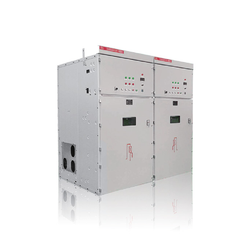
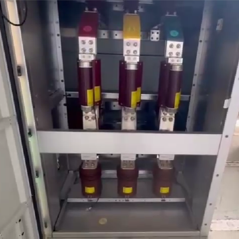
UFCL-limiter switchgear


Rated   voltage

kV

7.2

12

17.5

24

36

40.5

Rated   current

A

1250-6300

1250-4000

1250-3150

Rated   frequency

Hz

50/60

Rated   power-frequency withstand voltage

kV

20

28

38

50

70

95

Rated   lightning impulse withstand voltage

kV

60

75

95

125

170

185

Rated   auxiliary voltage

V

AC220/230

Installation   type

Cabinet type


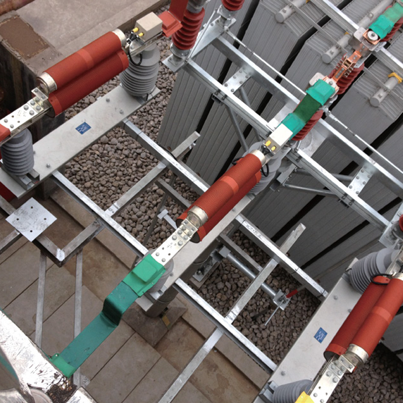
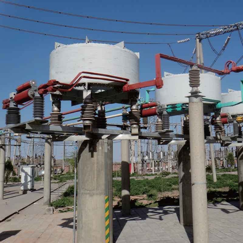
UFCL-limiter in loose equipment supply

Rated   voltage

kV

7.2

12

17.5

24

36

40.5

Rated   current

A

1250-6300

1250-4000

1250-3150

Rated   frequency

Hz

50/60

Rated   short-circuit breaking current

kA rms

Up to200

Rated   power-frequency withstand voltage

kV

20

28

38

50

70

95

Rated   lightning impulse withstand voltage

kV

60

75

95

125

170

185

Tripping   time

ms

<1

Total   operating time

ms

<10

Peak   current limiting ratio

%

15-50

Rated   auxiliary voltage

V

DC 110/220;AC110/220/230

Installation   type

Install in the form of loose parts


If you need to know about more parameters and application, Please check the model selection manual.↓↓↓ 

Know your supplier
RW Energy
Zhejiang Rockwell Energy Technology Co., Ltd. is an international enterprise specializing in the research, development and manufacturing of recloser controllers, power quality management, power monitoring systems and other high-end power equipment. In today's critical period of global energy transition and power system upgrading, the company has gathered a group of top talents in the fields of power engineering, automation control, software development, etc., who carry the enthusiasm and persistence for the power business, and are committed to overcoming the complex problems in the power system, and promoting the intelligent development of the power industry with innovative technology. Mission: To make global electricity smarter, more reliable and more efficient with innovative technology. Vision: To be the leader in global power intelligence.
Main Categories
High Voltage Electrical Apparatus/New energy/Tester
Business Type
Design/Manufacture/Sales
Highest Annual Export (USD)
$100000000
Professional Experience
12 years
Workplace
30000m²
占位
占位
Documents
Restricted.
Ultra-Fast Current Limiter Data sheet
White paper English
Consulting
Related Products
Related Knowledges
Cost Differences and Performance Comparison of 35kV New Energy Transformers Based on Dry-Type, Mineral Oil, and Vegetable Oil
For users, when purchasing a 35kV new energy transformer, choosing between dry-type, mineral oil-filled, or vegetable oil-filled types involves multiple considerations. These include user habits, maintenance-free performance, safety and fire resistance, volume and weight, among others. However, cost differences are undoubtedly one of the most crucial factors.To illustrate the issue intuitively, this paper selects a three-level energy efficiency dual-winding new energy transformer with a rated ca
Ron
07/26/2025
What is the connection group of a transformer?
Transformer Connection GroupThe connection group of a transformer refers to the phase difference between the primary and secondary voltages or currents. It is determined by the winding directions of the primary and secondary coils, the labeling of their start and end terminals, and the connection mode. Expressed in a clock-like format, there are 12 groups in total, numbered from 0 to 11.The DC method is commonly used to measure the transformer's connection group, mainly to verify whether the con
Vziman
07/26/2025
Working Voltage in Power System
Working VoltageThe term "working voltage" refers to the maximum voltage that a device can withstand without sustaining damage or burning out, while ensuring the reliability, safety, and proper operation of both the device and associated circuits.For long-distance power transmission, the use of high voltage is advantageous. In AC systems, maintaining a load power factor as close to unity as possible is also economically necessary. Practically, heavy currents are more challenging to handle than hi
Encyclopedia
07/26/2025
What is Steady State Stability in Power System?
Definition of Steady State StabilitySteady state stability is defined as the capability of an electric power system to sustain its initial operating condition following a small disturbance, or to converge to a state closely approximating the initial condition when the disturbance persists. This concept holds critical significance in power system planning and design, the development of specialized automatic control devices, the commissioning of new system components, and the adjustment of operati
Edwiin
07/26/2025
What is the sequence for powering down the transformer?
The sequence for shutting down a main transformer is as follows: when de-energizing, the load side should be shut down first, followed by the power supply side. For energizing operations, the reverse order applies: the power supply side is energized first, then the load side. This is because: Energizing from the power supply side to the load side makes it easier to identify the fault range and take prompt judgment and handling measures in case of a fault, preventing the fault from spreading or e
Rockwell
07/26/2025
What are the methods for switching operations of station transformers?
Let's take an auxiliary power system with two station transformers as an example. When one station transformer needs to be out of service, there are two operation methods: non-interruptive power supply and instantaneous power interruption. Generally, the method of instantaneous power interruption on the low-voltage side is preferred.The operation method for instantaneous power interruption on the low-voltage side is as follows:Open the 380V power incoming circuit breaker of the corresponding sec
Vziman
07/26/2025
×
Inquiry
Download
IEE-Business is dedicated to serving the personnel in the global power industry.
Join IEE-Business, not only can you discover power equipment and power knowledge, but also canhnd like - minded friends!