Essential Nodes And Essential Branches

Electrical4u
03/13/2024

What is an Essential Node?

A node is defined as a point where two or more circuit elements are connected. An essential node is a particular type of node where three or more elements are connected. An essential node is a useful node to consider in circuit analysis.

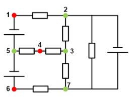
For example, in the below circuit, there is a total of seven nodes. Out of these seven nodes, there are four essential nodes that have been marked in green. The remaining three regular nodes have been marked in red.

an essential node.png

What is an Essential Branch?

A branch is defined as a path that connects two or more nodes. An essential branch is a particular type of branch that connects essential nodes without passing an essential node.

That is to say that while an essential branch may pass through a regular node, it may not pass through an essential node. If this sounds confusing, take a look at the example below.

The circuit diagram below contains seven essential branches (B1 to B7).

image.png

Notice that B3 is an essential branch and that it passes through the non-essential node 4 (see prior diagram for node labeling).

Whereas the essential branches B4 and B5 are distinct essential branches. An essential branch does not exist between the top node (node 2 in the prior diagram) and the bottom node (node 7 in the prior diagram), because there exists an essential node in between these nodes (node 3 in the prior diagram).

Hence node 3, an essential node, “breaks up” the larger branch into two essential branches.

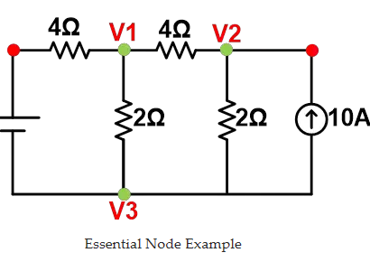
Essential Node Example

Essential nodes are very useful in circuit analysis. In nodal analysis, we can use only essential nodes to solve the circuit.

Let’s understand the impotence of essential nodes in circuit analysis with an example.

In this example, we will solve a circuit using the nodal analysis method. And in this method, we use only essential nodes.

image.png

But for simple calculation, the essential node that is connected with a greater number of branches is chosen. And here, node V3 is a reference node.

n = the number of essential nodes in a circuit

Hence, the number of equations needed to solve this circuit is n-1=2.

At node-V1;\[ \frac{V1-10}{4} + \frac{V1}{2} + \frac{V1-V2}{4} = 0 \]

At node V2;

  \[ \frac{V2-V1}{4} + \frac{V2}{2} -10 = 0 \]

By solving these two equations, we can find the value of node voltages V1 and V.

  \[ V1 = 6.363 \]

 \[ V2 = 15.454 \]

Essential Branch Example

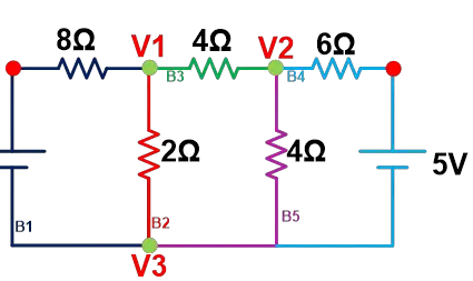
Essential branches are useful in mesh analysis. See the circuit diagram below for a simple example.


image.png
Essential Branch Example


Here:

  • The total number of branches is 7

  • The total number of essential branches is 5 (B1 to B5)

  • The total number of essential nodes is 3 (V1 to V3)

Hence, the number of equations we need to solve this circuit is b-(n-1).

Here, for this example, the total number of equations required to solve this circuit is 3.

So, we apply KVL to each loop.

Loop-1

  \[ 10 = 10I_1 -  2I_2 \]

Loop-2

  \[ 0 = 10I_2 - 2I_1 - 4I_3 \]

Loop-3

  \[ -5 = 10I_3 - 4I_2 \]

By solving these equations, we get the values of;

 \[ I_1 = 1A \]

  \[ I_2 = 0A \]

  \[ I_3 = -0.5A \]

From the above values, we can find other circuit parameters like power offered by a voltage source, the current flowing through and the voltage across each element, etc.

Source: Electrical4u.

Statement: Respect the original, good articles worth sharing, if there is infringement please contact delete.

Electrical4u

Electrical4U is dedicated to the teaching and sharing of all things related to electrical and electronics engineering.

Frequency division method for measuring grid-to-ground insulation parameters
The frequency division method enables the measurement of grid-to-ground parameters by injecting a current signal of a different frequency into the open delta side of the potential transformer (PT).This method is applicable to ungrounded systems; however, when measuring the grid-to-ground parameters of a system where the neutral point is grounded via an arc suppression coil, the arc suppression coil must be disconnected from operation beforehand. Its measurement principle is shown in Figure 1.As
Leon
07/25/2025
The insulation parameters of the power grid to ground are measured by the tuning method
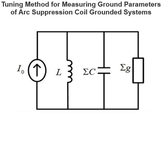
The tuning method is suitable for measuring the ground parameters of systems where the neutral point is grounded via an arc suppression coil, but not applicable to ungrounded neutral point systems. Its measurement principle involves injecting a current signal with continuously varying frequency from the secondary side of the Potential Transformer (PT), measuring the returned voltage signal, and identifying the system's resonant frequency.During the frequency sweeping process, each injected heter
Leon
07/25/2025
Effect of Transition Resistance at the Grounding Point on the Rising Speed of Zero - sequence Voltage
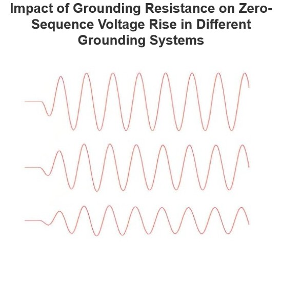
In an arc - suppression coil grounding system, the rising speed of the zero - sequence voltage is greatly affected by the value of the transition resistance at the grounding point. The larger the transition resistance at the grounding point, the slower the rising speed of the zero - sequence voltage.In an ungrounded system, the transition resistance at the grounding point has basically no impact on the rising speed of the zero - sequence voltage.Simulation Analysis: Arc - suppression Coil Ground
Leon
07/24/2025
Equivalent Circuit of a Transformer
The equivalent circuit diagram of any device can be extremely useful for predicting how the device will behave under different operating conditions. It is essentially a circuit - based depiction of the equations that describe the device's performance.The simplified equivalent circuit of a transformer is constructed by representing all of the transformer's parameters on either the secondary side or the primary side. The equivalent circuit diagram of the transformer is presented below:Let the equi
Edwiin
06/03/2025
Inquiry
Download
IEE-Business is dedicated to serving the personnel in the global power industry.
Join IEE-Business, not only can you discover power equipment and power knowledge, but also canhnd like - minded friends!