Nodal Analysis in Electric Circuits

Electrical4u
03/13/2024

Definition of Nodal Analysis

Nodal analysis is a method that provides a general procedure for analyzing circuits using node voltages as the circuit variables. Nodal Analysis is also called the Node-Voltage Method.
Some Features of Nodal Analysis are as

  • Nodal Analysis is based on the application of the Kirchhoff’s Current Law (KCL).

  • Having ‘n’ nodes there will be ‘n-1’ simultaneous equations to solve.

  • Solving ‘n-1’ equations all the nodes voltages can be obtained.

  • The number of non reference nodes is equal to the number of Nodal equations that can be obtained.

Types of Nodes in Nodal Analysis

  • Non Reference Node – It is a node which has a definite Node Voltage. e.g. Here Node 1 and Node 2 are the Non Reference nodes

  • Reference Node – It is a node which acts a reference point to all the other node. It is also called the Datum Node.

Types of Reference Nodes

  1. Chassis Ground – This type of reference node acts a common node for more than one circuits.
    chassis ground

  2. Earth Ground – When earth potential is used as a reference in any circuit then this type of reference node is called Earth Ground.

earth ground

Solving of Circuit Using Nodal Analysis

Basic Steps Used in Nodal Analysis

  1. Select a node as the reference node. Assign voltages V1, V2… Vn-1 to the remaining nodes. The voltages are referenced with respect to the reference node.

  2. Apply KCL to each of the non reference nodes.

  3. Use Ohm’s law to express the branch currents in terms of node voltages.

nodal analysis

Node Always assumes that current flows from a higher potential to a lower potential in resistor. Hence, current is expressed as follows

IV. After the application of Ohm’s Law get the ‘n-1’ node equations in terms of node voltages and resistances.

V. Solve ‘n-1’ node equations for the values of node voltages and get the required node Voltages as result.

Nodal Analysis with Current Sources

Nodal analysis with current sources is very easy and it is discussed with a example below.

Example: Calculate Node Voltages in following circuit
nodal analysis
In the following circuit we have 3 nodes from which one is reference node and other two are non reference nodes – Node 1 and Node 2.

Step I. Assign the nodes voltages as v1 and 2 and also mark the directions of branch currents with respect to the reference nodes
nodal analysis
Step II. Apply KCL to Nodes 1 and 2
KCL at Node 1
KCL at Node 2
Step III. Apply Ohm’s Law to KCL equations
Ohm’s law to KCL equation at Node 1

Simplifying the above equation we get,

• Now, Ohm’s Law to KCL equation at Node 2

Simplifying the above equation we get

Step IV. Now solve the equations 3 and 4 to get the values of v1 and v2 as,
Using elimination method

And substituting value v2 = 20 Volts in equation (3) we get-

Hence node voltages are as v1 = 13.33 Volts and v2 = 20 Volts.

Nodal Analysis with Voltage Sources

Case I. If a voltage source is connected between the reference node and a non reference node, we simply set the voltage at the non-reference node equal to the voltage of the voltage source and its analysis can be done as we done with current sources. v1 = 10 Volts.

Case II. If the voltage source is between the two non reference nodes then it forms a supernode whose analysis is done as following

Supernode Analysis

Definition of Super Node

Whenever a voltage source (Independent or Dependent) is connected between the two non reference nodes then these two nodes form a generalized node called the Super node. So, Super node can be regarded as a surface enclosing the voltage source and its two nodes.
supernode
In the above Figure 5V source is connected between two non reference nodes Node – 2 and Node – 3. So here Node – 2 and Node – 3 form the Super node.

Properties of Supernode

  • Always the difference between the voltage of two non reference nodes is known at Supernode.

  • A supernode has no voltage of its own

  • A supernode requires application of both KCL and KVL to solve it.

  • Any element can be connected in parallel with the voltage source forming the supernode.

  • A Supernode satisfies the KCL as like a simple node.

How Solve Any Circuit Containing Supernode

Let’s take a example to understand how to solve circuit containing Supernode
circuit containing supernode
Here 2V voltage source is connected between Node-1 and Node-2 and it forms a Supernode with a 10Ω resistor in parallel.
Note – Any element connected in parallel with the voltage source forming Super node doesn’t make any difference because v2– v1 = 2V always whatever may be the value of resistor. Thus 10 Ω can be removed and circuit is redrawn and applying KCL to the supernode as shown in figure gives,

Expressing and in terms of the node voltages.


From Equation 5 and 6 we can write as

Hence, v1 = – 7.333V and v2 = – 5.333V which is required answer.

Source: Electrical4u.

Statement: Respect the original, good articles worth sharing, if there is infringement please contact delete.


Electrical4u

Electrical4U is dedicated to the teaching and sharing of all things related to electrical and electronics engineering.

Frequency division method for measuring grid-to-ground insulation parameters
The frequency division method enables the measurement of grid-to-ground parameters by injecting a current signal of a different frequency into the open delta side of the potential transformer (PT).This method is applicable to ungrounded systems; however, when measuring the grid-to-ground parameters of a system where the neutral point is grounded via an arc suppression coil, the arc suppression coil must be disconnected from operation beforehand. Its measurement principle is shown in Figure 1.As
Leon
07/25/2025
The insulation parameters of the power grid to ground are measured by the tuning method
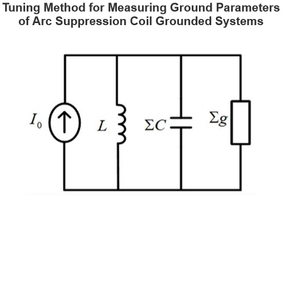
The tuning method is suitable for measuring the ground parameters of systems where the neutral point is grounded via an arc suppression coil, but not applicable to ungrounded neutral point systems. Its measurement principle involves injecting a current signal with continuously varying frequency from the secondary side of the Potential Transformer (PT), measuring the returned voltage signal, and identifying the system's resonant frequency.During the frequency sweeping process, each injected heter
Leon
07/25/2025
Effect of Transition Resistance at the Grounding Point on the Rising Speed of Zero - sequence Voltage
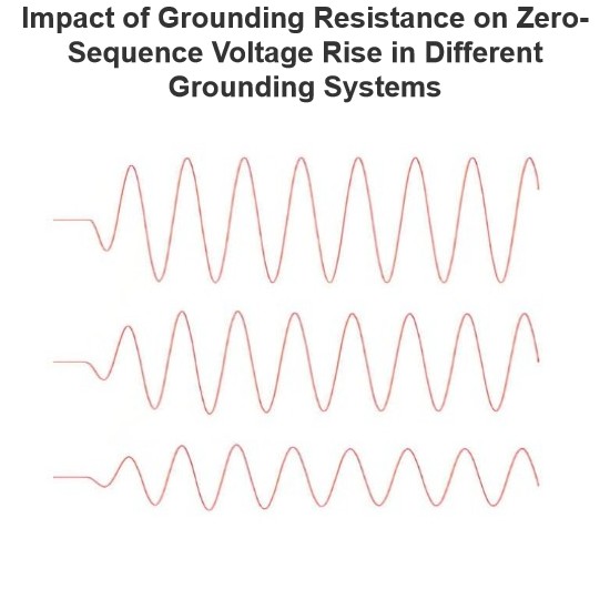
In an arc - suppression coil grounding system, the rising speed of the zero - sequence voltage is greatly affected by the value of the transition resistance at the grounding point. The larger the transition resistance at the grounding point, the slower the rising speed of the zero - sequence voltage.In an ungrounded system, the transition resistance at the grounding point has basically no impact on the rising speed of the zero - sequence voltage.Simulation Analysis: Arc - suppression Coil Ground
Leon
07/24/2025
Equivalent Circuit of a Transformer
The equivalent circuit diagram of any device can be extremely useful for predicting how the device will behave under different operating conditions. It is essentially a circuit - based depiction of the equations that describe the device's performance.The simplified equivalent circuit of a transformer is constructed by representing all of the transformer's parameters on either the secondary side or the primary side. The equivalent circuit diagram of the transformer is presented below:Let the equi
Edwiin
06/03/2025
Inquiry
Download
IEE-Business is dedicated to serving the personnel in the global power industry.
Join IEE-Business, not only can you discover power equipment and power knowledge, but also canhnd like - minded friends!