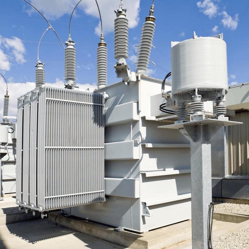
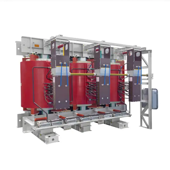
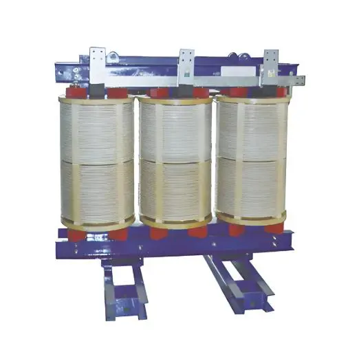
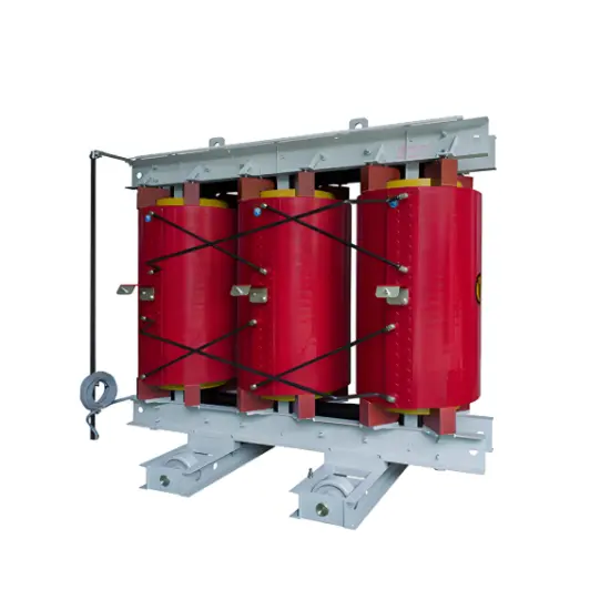
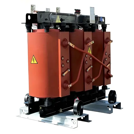
Transformer Winding Resistance Testing

Encyclopedia
09/19/2024

Winding Resistance Test Definition


The winding resistance test of a transformer checks the health of transformer windings and connections by measuring resistance.


Procedure of Transformer Winding Resistance Measurement


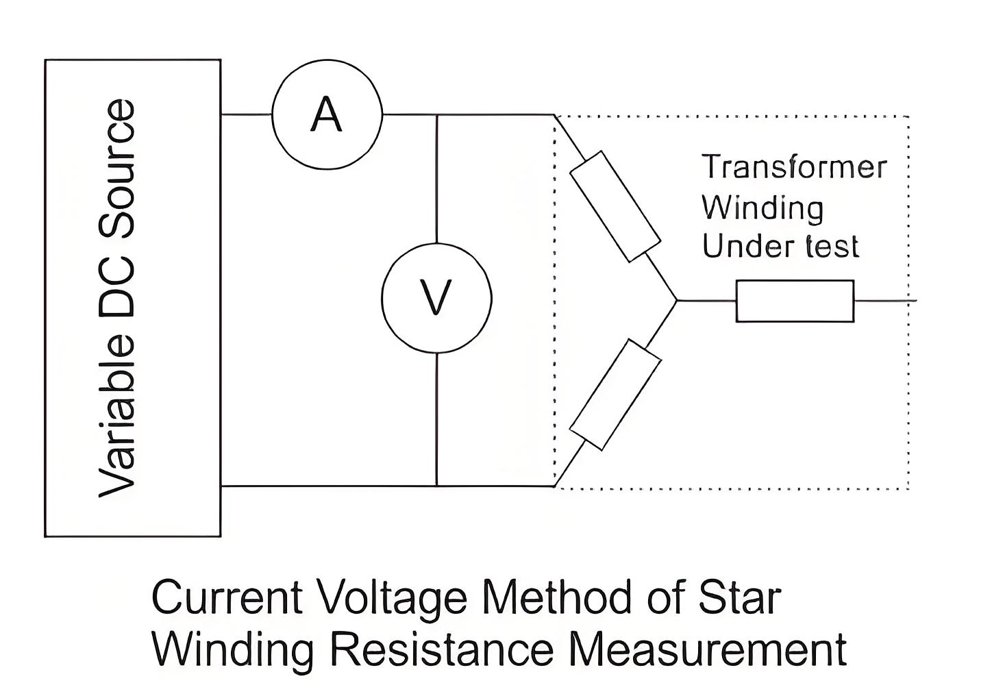
For star connected winding, the resistance shall be measured between the line and neutral terminal.


For star connected autotransformers the resistance of the HV side is measured between HV terminal and IV terminal, then between IV terminal and the neutral.


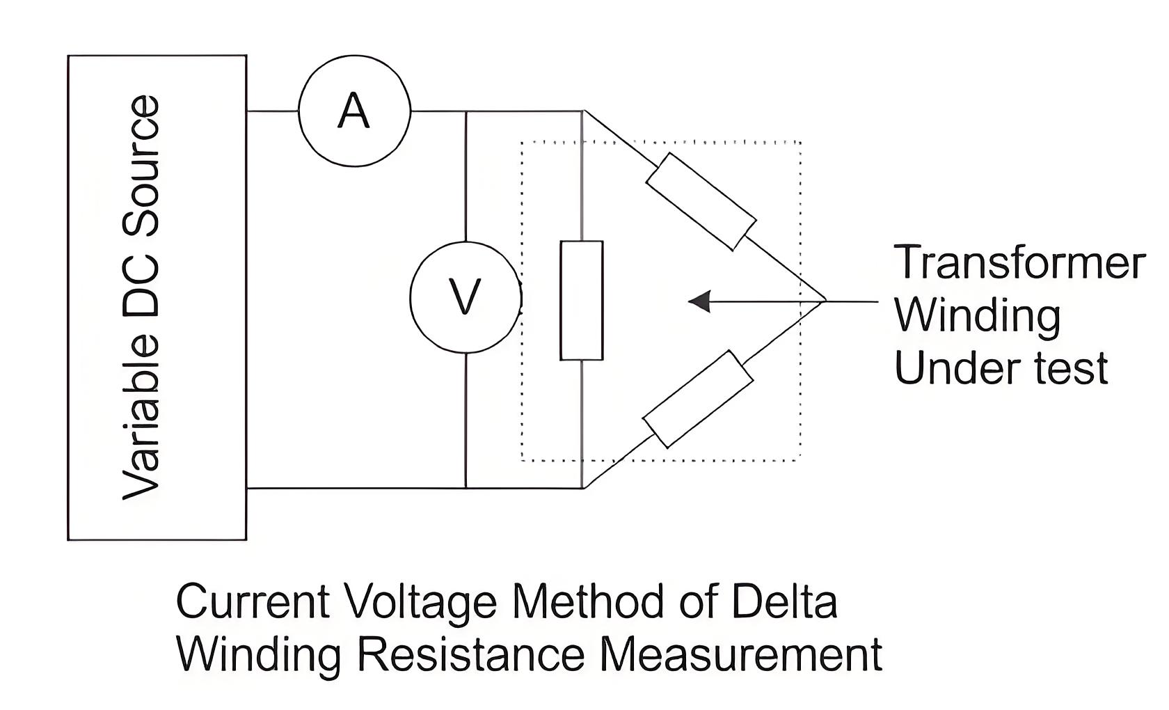
For delta connected windings, measurement of winding resistance shall be done between pairs of line terminals. As in delta connection the resistance of individual winding can not be measured separately, the resistance per winding shall be calculated as per the following formula:


Resistance per winding = 1.5 × Measured value


The resistance is measured at ambient temperature and converted to resistance at 75°C for comparison with design values, past results, and diagnostics.


Winding Resistance at standard temperature of 75oC


6c881862d78aee85f5699e17505b1bed.jpeg


Rt = Winding resistance at temperature t

t = Winding temperature


Generally, transformer windings are immersed in insulation liquid and covered with paper insulation, hence it is impossible to measure the actual winding temperature in a de-energizing transformer at the time of transformer winding resistance measurement. An approximation is developed to calculate the temperature of winding at that condition, as follows


Temperature of winding = Average temperature of insulating oil


The average temperature of insulating oil should be taken 3 to 8 hours after de-energizing transformer and when the difference between top and bottom oil temperatures becomes less than 5oC.


The resistance can be measured by a simple voltmeter ammeter method, Kelvin Bridge meter or automatic winding resistance measurement kit (ohm meter, preferably 25 Amps kit).


Caution for voltmeter ammeter method: Current shall not exceed 15% of the rated current of the winding. Large values may cause inaccuracy by heating the winding and thereby changing its temperature and resistance.


Note: The measurement of winding resistance of a transformer shall be carried out at each tap.


Current Voltage Method of Measurement of Winding Resistance


The transformer winding resistances can be measured by current voltage method. In this method of measurement of winding resistance, the test current is injected to the winding and corresponding voltage drop across the winding is measured. By applying simple Ohm’s law i.e. Rx = V ⁄ I, one can easily determine the value of resistance.


Procedure of Current Voltage Method of Measurement of Winding Resistance


  • Before measurement, the transformer should be off and without excitation for 3 to 4 hours. This allows the winding temperature to match the oil temperature.


  • Measurement is done with D.C.


  • To minimize observation errors, polarity of the core magnetization shall be kept constant during all resistance readings.


  • Voltmeter leads shall be independent of the current leads to protect it from high voltages which may occur during switching on and off the current circuit


  • The readings shall be taken after the current and voltage have reached steady state values. In some cases this may take several minutes depending upon the winding impedance.


  • The test current shall not exceed 15% of the rated current of the winding. Large values may cause inaccuracy by heating the winding and thereby changing its resistance.


  • For expressing resistance, the corresponding temperature of the winding at the time of measurement must be mentioned along with resistance value. As we said earlier that after remaining in switch off condition for 3 to 4 hours, the winding temperature would become equal to oil temperature. The oil temperature at the time of testing is taken as the average of top oil and bottom oil temperatures of transformer.


6a79f140457d1ddcd4b8b0eb98fdf28a.jpeg

  • For star connected three-phase winding, the resistance per phase would be half of the measured resistance between two line terminals of the transformer


  • For delta connected three-phase winding, the resistance per phase would be 0.67 times of measured resistance between two line terminals of the transformer.


  • This current voltage method of measurement of winding resistance of transformer should be repeated for each pair of line terminals of winding at every tap position.


b8ff38fb6e37b6b86ef37578d67893ba.jpeg


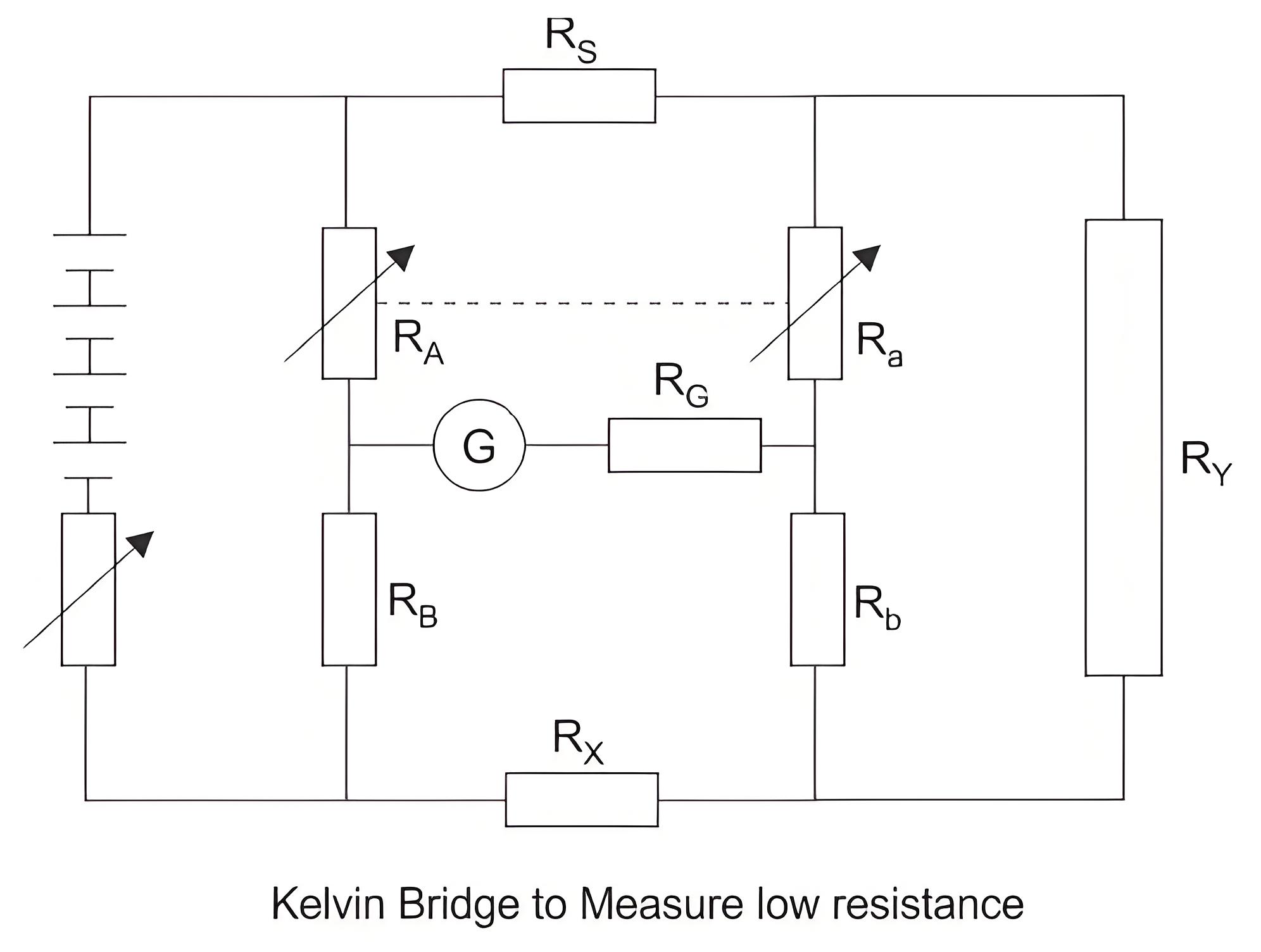
Bridge Method of Measurement of Winding Resistance


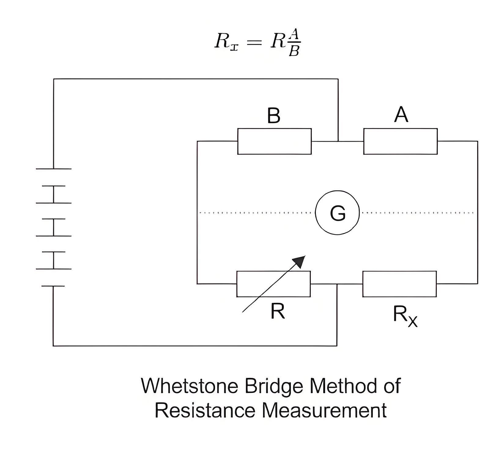
The main principle of the bridge method is based on comparing an unknown resistance with a known resistance. When currents flowing through the arms of the bridge circuit become balanced, the reading of galvanometer shows zero deflection that means at balanced condition no current will flow through the galvanometer.


A very small value of resistance (in milli-ohms range) can be accurately measured by the Kelvin bridge method whereas for higher value Wheatstone bridge method of resistance measurement is applied. In bridge method of measurement of winding resistance, the errors are minimized.


200599850ac781b2c8ed52488080e293.jpeg

255babd1174f5879d58d724b8e390655.jpeg


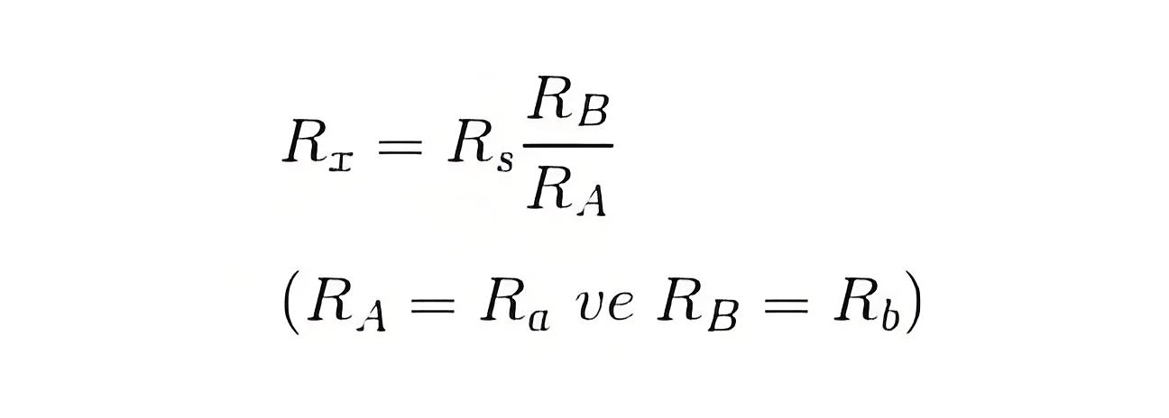
The resistance measured by Kelvin bridge


314e17193f20d82e8a9c3a9c831ea7cb.jpeg

All other steps to be taken during transformer winding resistance measurement in these methods are similar to that of current voltage method of measurement of winding resistance of transformer, except the measuring technique of resistance.


The resistance measured by Wheatstone bridge,


fef819b04665435cd6791860d3f2c22f.jpeg

Encyclopedia

The Electricity Encyclopedia is dedicated to accelerating the dissemination and application of electricity knowledge and adding impetus to the development and innovation of the electricity industry.

Cost Differences and Performance Comparison of 35kV New Energy Transformers Based on Dry-Type, Mineral Oil, and Vegetable Oil
For users, when purchasing a 35kV new energy transformer, choosing between dry-type, mineral oil-filled, or vegetable oil-filled types involves multiple considerations. These include user habits, maintenance-free performance, safety and fire resistance, volume and weight, among others. However, cost differences are undoubtedly one of the most crucial factors.To illustrate the issue intuitively, this paper selects a three-level energy efficiency dual-winding new energy transformer with a rated ca
Ron
07/26/2025
What is the connection group of a transformer?
Transformer Connection GroupThe connection group of a transformer refers to the phase difference between the primary and secondary voltages or currents. It is determined by the winding directions of the primary and secondary coils, the labeling of their start and end terminals, and the connection mode. Expressed in a clock-like format, there are 12 groups in total, numbered from 0 to 11.The DC method is commonly used to measure the transformer's connection group, mainly to verify whether the con
Vziman
07/26/2025
What is the sequence for powering down the transformer?
The sequence for shutting down a main transformer is as follows: when de-energizing, the load side should be shut down first, followed by the power supply side. For energizing operations, the reverse order applies: the power supply side is energized first, then the load side. This is because: Energizing from the power supply side to the load side makes it easier to identify the fault range and take prompt judgment and handling measures in case of a fault, preventing the fault from spreading or e
Rockwell
07/26/2025
What are the methods for switching operations of station transformers?
Let's take an auxiliary power system with two station transformers as an example. When one station transformer needs to be out of service, there are two operation methods: non-interruptive power supply and instantaneous power interruption. Generally, the method of instantaneous power interruption on the low-voltage side is preferred.The operation method for instantaneous power interruption on the low-voltage side is as follows:Open the 380V power incoming circuit breaker of the corresponding sec
Vziman
07/26/2025
Inquiry
Download
IEE-Business is dedicated to serving the personnel in the global power industry.
Join IEE-Business, not only can you discover power equipment and power knowledge, but also canhnd like - minded friends!