What are the main causes for distribution transformer failure?

Encyclopedia
11/01/2024

Main Causes of Distribution Transformer Failures

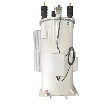
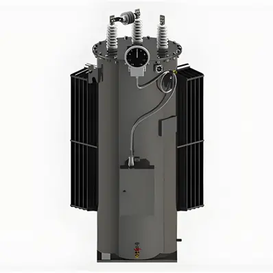
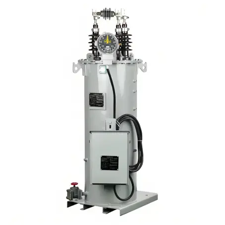
Distribution transformers are essential components in power systems, used to convert high-voltage electricity to low-voltage electricity for end-users. Transformer failures can be caused by various factors. The following are some common reasons for distribution transformer failures:

1. Overloading

  • Cause: Operating the transformer beyond its rated capacity for extended periods.

  • Consequence: Excessive heat generation, leading to the degradation of insulation materials, which can ultimately result in insulation breakdown and short circuits.

2. Insulation Aging

  • Cause: Long-term operation, high temperatures, humidity, and chemical corrosion can degrade insulation materials.

  • Consequence: Reduced insulation performance, leading to leakage, short circuits, or breakdowns.

3. Overvoltage

  • Cause: Lightning strikes, grid faults, and switching surges.

  • Consequence: Overvoltage can cause insulation breakdown, leading to internal short circuits or ground faults.

4. Short Circuits

  • Cause: External short circuits (e.g., line-to-line or line-to-ground faults) and internal short circuits (e.g., turn-to-turn short circuits in windings).

  • Consequence: Generation of massive short-circuit currents, which can damage or burn out the transformer.

5. Mechanical Damage

  • Cause: Impact and vibration during transportation and installation.

  • Consequence: Deformation of windings, broken leads, or damaged insulation.

6. Deterioration of Oil Quality

  • Cause: Contamination, moisture ingress, and oxidation of transformer oil.

  • Consequence: Degradation of the oil's insulating properties, leading to internal short circuits or breakdowns.

7. Cooling System Failure

  • Cause: Malfunction of cooling equipment such as fans and oil pumps.

  • Consequence: Poor heat dissipation, resulting in excessive temperature rise and accelerated aging of insulation materials.

8. Manufacturing Defects

  • Cause: Poor design, substandard materials, and manufacturing process defects.

  • Consequence: Various faults during operation, such as localized overheating and poor insulation.

9. Environmental Factors

  • Cause: Harsh environmental conditions such as high temperatures, high humidity, salt spray, and dust.

  • Consequence: Accelerated aging of insulation materials, leading to a decline in insulation performance.

10. Improper Maintenance

  • Cause: Lack of regular maintenance, delayed repairs, and improper operation.

  • Consequence: Degradation of transformer performance and potential failure.

11. Harmonic Pollution

  • Cause: Harmonic currents generated by non-linear loads.

  • Consequence: Increased transformer losses and temperature rise, leading to overheating and insulation damage.

12. Grounding Faults

  • Cause: Poor grounding systems and high grounding resistance.

  • Consequence: Abnormal internal potentials in the transformer, leading to faults.

Summary

Distribution transformer failures can be caused by a variety of factors, including overloading, insulation aging, overvoltage, short circuits, mechanical damage, deterioration of oil quality, cooling system failures, manufacturing defects, environmental factors, improper maintenance, harmonic pollution, and grounding faults. To ensure the safe and reliable operation of transformers, regular maintenance and inspections are necessary to identify and address potential issues promptly.

Encyclopedia

The Electricity Encyclopedia is dedicated to accelerating the dissemination and application of electricity knowledge and adding impetus to the development and innovation of the electricity industry.

Cost Differences and Performance Comparison of 35kV New Energy Transformers Based on Dry-Type, Mineral Oil, and Vegetable Oil
For users, when purchasing a 35kV new energy transformer, choosing between dry-type, mineral oil-filled, or vegetable oil-filled types involves multiple considerations. These include user habits, maintenance-free performance, safety and fire resistance, volume and weight, among others. However, cost differences are undoubtedly one of the most crucial factors.To illustrate the issue intuitively, this paper selects a three-level energy efficiency dual-winding new energy transformer with a rated ca
Ron
07/26/2025
What is the connection group of a transformer?
Transformer Connection GroupThe connection group of a transformer refers to the phase difference between the primary and secondary voltages or currents. It is determined by the winding directions of the primary and secondary coils, the labeling of their start and end terminals, and the connection mode. Expressed in a clock-like format, there are 12 groups in total, numbered from 0 to 11.The DC method is commonly used to measure the transformer's connection group, mainly to verify whether the con
Vziman
07/26/2025
What is the sequence for powering down the transformer?
The sequence for shutting down a main transformer is as follows: when de-energizing, the load side should be shut down first, followed by the power supply side. For energizing operations, the reverse order applies: the power supply side is energized first, then the load side. This is because: Energizing from the power supply side to the load side makes it easier to identify the fault range and take prompt judgment and handling measures in case of a fault, preventing the fault from spreading or e
Rockwell
07/26/2025
What are the methods for switching operations of station transformers?
Let's take an auxiliary power system with two station transformers as an example. When one station transformer needs to be out of service, there are two operation methods: non-interruptive power supply and instantaneous power interruption. Generally, the method of instantaneous power interruption on the low-voltage side is preferred.The operation method for instantaneous power interruption on the low-voltage side is as follows:Open the 380V power incoming circuit breaker of the corresponding sec
Vziman
07/26/2025
Inquiry
Download
IEE-Business is dedicated to serving the personnel in the global power industry.
Join IEE-Business, not only can you discover power equipment and power knowledge, but also canhnd like - minded friends!