| Brand | Wone Store |
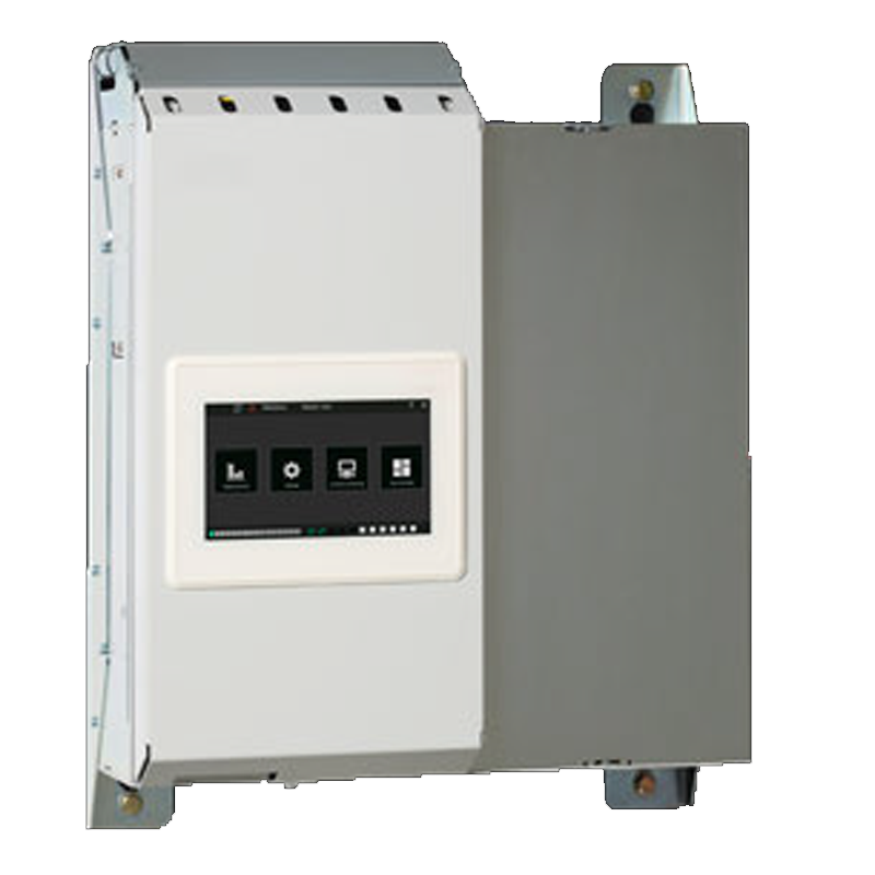
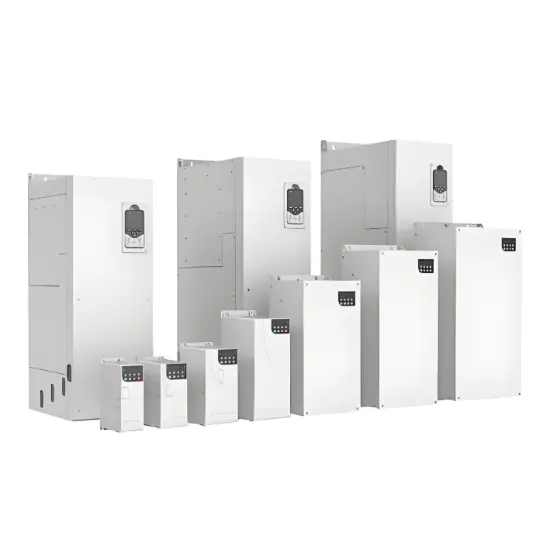
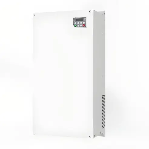
| Model NO. | PQF Series Active filters |
| Rated voltage | 400V |
| Rated normal current | 60A |
| Mounting type | Wall-mounted |
| Series | PQF Series |
Overview
Operational efficiency
● Fewer events of equipment failure due to poor power quality of the network, thereby creating trouble-free and effcient operations
● Improved performance of loads thanks to a cleaner supply network
Cost effciency
● Increased lifetime of the equipment enabling lower plantrunning costs
● Compliance with the strictest regulations (such as individual harmonic limits) thanks to the unique control concept, thereby avoiding penalties and/or refusal by utilities to connect installations to the electrical grid
Energy effciency
Lower energy losses in cables and transformers and hence a higher efficiency of the system but also a reduction of CO2 emissions
Better safety of the installations and better operation
Of sensitive loads as the voltage drop between neutral and earth is reduced
Harmonic filtering effciency
The active filters PQF have high filtering efficiency due to the following features:
● Capability of filtering up to 20 harmonics simultaneously
● Selection of harmonics up to the 50th harmonic
● Harmonic attenuation factor better than 97%
● Desired harmonic levels can be preset for each selectedharmonic
Reactive power compensation
PQF can perform precise stepless reactive power compensation of both inductive and capacitive loads. The target cos φ is programmable from 0.6 (inductive) to 0.6 (capacitive) which makes PQF an alternative to a conventional capacitor bank. Moreover this allows compensation of loads fed by generators without the risk of overcompensation. In addition, capacitiveloads can also be compensated.
Load balancing
This feature is available in both 3 and 4-wire systems between phases and between phase and neutral. It helps to improve voltage unbalance on the phases and reduction of neutral current which increases the safety of the installation and allows sensitive loads to operate.
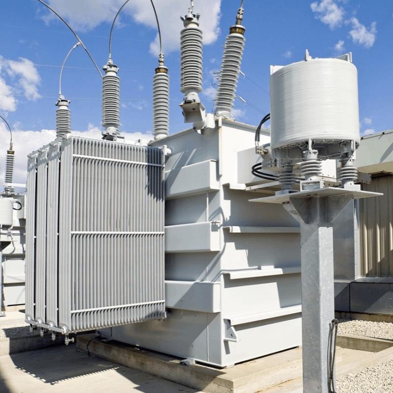
Application
Active harmonic filters installed in parallel to the power feed cancelled the harmonic currents allowing ‘clean’ ECG recordings. An Australian hospital, located in Melbourne, Victoria, is one
of the country’s leading public hospitals established in 1848. It is a major teaching hospital for tertiary health care with a reputation in clinical research. It has one of the largest.Emergency
Technology parameters