What are the main differences between AC and DC current in terms of their effects on conductors, capacitors, and transformers?

Encyclopedia
02/15/2025

Differences in the Impact of AC and DC on Conductors, Capacitors, and Transformers

The effects of alternating current (AC) and direct current (DC) on conductors, capacitors, and transformers differ significantly, primarily in the following aspects:

Impact on Conductors

  • Skin Effect: In AC circuits, due to electromagnetic induction, the current tends to flow near the surface of the conductor, a phenomenon known as the skin effect. This results in a reduced effective cross-sectional area of the conductor, increased resistance, and thus more energy loss. In DC circuits, the current is uniformly distributed throughout the conductor's cross-section, avoiding the skin effect.

  • Proximity Effect: When a conductor is close to another current-carrying conductor, AC causes the current to redistribute itself, leading to the proximity effect. This increases the conductor's resistance and introduces additional energy losses. DC is not affected by this phenomenon.

Impact on Capacitors

  • Charging and Discharging: AC causes capacitors to periodically charge and discharge, with voltage and current being 90 degrees out of phase. This allows capacitors to store and release energy and exhibit low impedance for high-frequency signals. In DC circuits, once the capacitor is fully charged to its maximum voltage, no further current flows through it.

  • Capacitive Reactance: Under AC, capacitors exhibit capacitive reactance, which depends on frequency and capacitance; higher frequencies result in lower reactance. In DC circuits, capacitors act as an open circuit, meaning infinite reactance.

Impact on Transformers

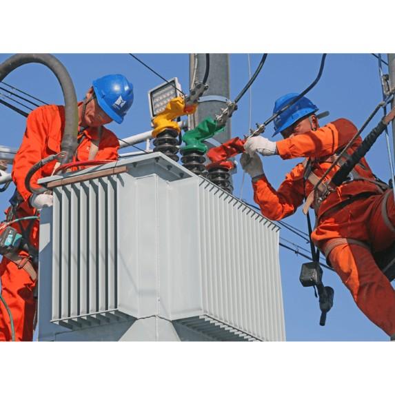
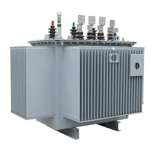
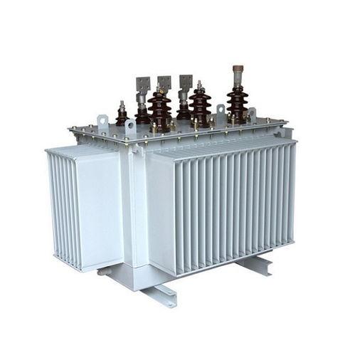
  • Operating Principle: Transformers operate based on the principle of electromagnetic induction, relying on changing magnetic fields to transfer energy. Only varying magnetic fields can induce electromotive force, so transformers are exclusively used with AC. DC cannot produce the necessary fluctuating magnetic flux within a transformer, rendering it incapable of performing voltage transformation.

  • Core Losses and Copper Losses: In AC conditions, transformers experience core losses (hysteresis and eddy current losses) and copper losses (energy lost due to winding resistance). While DC avoids core loss issues, it cannot function properly without a changing magnetic field.

In summary, the impacts of AC and DC on electrical components are determined by their respective characteristics, such as frequency and direction. These differences dictate the suitability of different types of power sources for various applications and technical requirements. By understanding these distinctions, engineers can better design and optimize electrical systems for specific needs.

Encyclopedia

The Electricity Encyclopedia is dedicated to accelerating the dissemination and application of electricity knowledge and adding impetus to the development and innovation of the electricity industry.

Cost Differences and Performance Comparison of 35kV New Energy Transformers Based on Dry-Type, Mineral Oil, and Vegetable Oil
For users, when purchasing a 35kV new energy transformer, choosing between dry-type, mineral oil-filled, or vegetable oil-filled types involves multiple considerations. These include user habits, maintenance-free performance, safety and fire resistance, volume and weight, among others. However, cost differences are undoubtedly one of the most crucial factors.To illustrate the issue intuitively, this paper selects a three-level energy efficiency dual-winding new energy transformer with a rated ca
Ron
07/26/2025
What is the connection group of a transformer?
Transformer Connection GroupThe connection group of a transformer refers to the phase difference between the primary and secondary voltages or currents. It is determined by the winding directions of the primary and secondary coils, the labeling of their start and end terminals, and the connection mode. Expressed in a clock-like format, there are 12 groups in total, numbered from 0 to 11.The DC method is commonly used to measure the transformer's connection group, mainly to verify whether the con
Vziman
07/26/2025
What is the sequence for powering down the transformer?
The sequence for shutting down a main transformer is as follows: when de-energizing, the load side should be shut down first, followed by the power supply side. For energizing operations, the reverse order applies: the power supply side is energized first, then the load side. This is because: Energizing from the power supply side to the load side makes it easier to identify the fault range and take prompt judgment and handling measures in case of a fault, preventing the fault from spreading or e
Rockwell
07/26/2025
What are the methods for switching operations of station transformers?
Let's take an auxiliary power system with two station transformers as an example. When one station transformer needs to be out of service, there are two operation methods: non-interruptive power supply and instantaneous power interruption. Generally, the method of instantaneous power interruption on the low-voltage side is preferred.The operation method for instantaneous power interruption on the low-voltage side is as follows:Open the 380V power incoming circuit breaker of the corresponding sec
Vziman
07/26/2025
Inquiry
Download
IEE-Business is dedicated to serving the personnel in the global power industry.
Join IEE-Business, not only can you discover power equipment and power knowledge, but also canhnd like - minded friends!