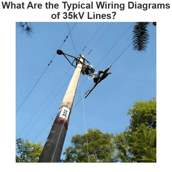
Typical Wiring Diagram of 35kV Line Radial π ConnectionWhen a 35kV line adopts a radial power grid structure, a single - side power supply or a double - side power supply radial type can be used according to the situation of the power supply points, and a loop - out interval is reserved at the end of the line.Typical Wiring Diagram of 35kV Line Radial T - ConnectionFor double - radial lines, it is advisable to select a double - side power supply. When the power supply points do not meet t
07/18/2025
Consult
Tip
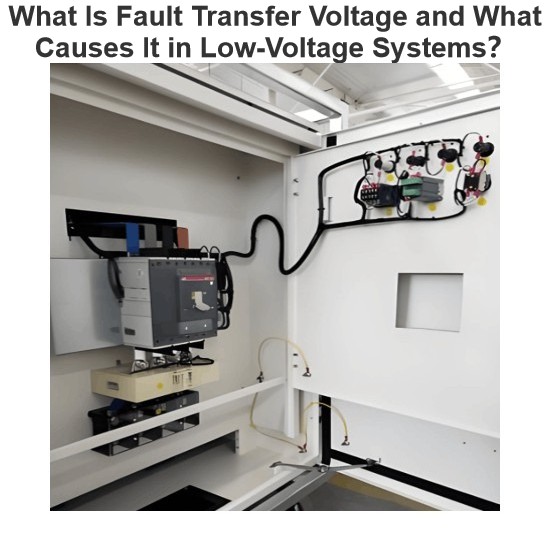
Fault Transfer VoltageIn low - voltage distribution systems, there is a type of personal electric shock accident where the accident occurrence point and the system fault point are not at the same location. This kind of accident occurs because after a ground fault happens elsewhere, the generated fault voltage is conducted to the metal casings of other equipment through the PE wire or PEN wire. When the fault voltage on the metal casing of the equipment is higher than the human - body safe voltag
07/18/2025
Consult
Tip
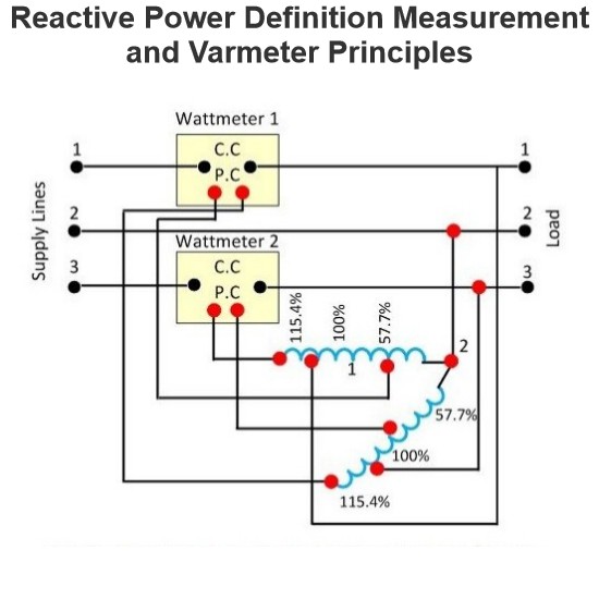
The power which exists in the circuit when the voltage and current are out of phase to each other, such type of power is known as the reactive power. The formula measures the reactive power in the circuitReactive Power Measurement & VarmetersReactive power measurement is critical as it indicates circuit power loss: low reactive power worsens load power factor, increasing system losses. Varmeters (volt-ampere reactive meters) measure reactive power and are categorized by circuit phases: Singl
07/17/2025
Consult
Tip
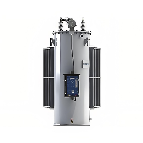
Hey everyone, I'm Blue — an electrical engineer with over 20 years of experience, currently working at ABB. My career has mainly focused on circuit breaker design, transformer management, and providing power system solutions for various utility companies.Today, someone asked the question: "What is a step voltage regulator?" Let me explain it in simple but professional terms.So, a step voltage regulator is basically a device used in power distribution systems to keep the voltage stable. Think of
07/11/2025
Consult
Tip

The typical electric power system network is categorized into three main components: generation, transmission, and distribution. Electric power is produced in power plants, which are often located far from load centers. As a result, transmission lines are employed to deliver power over long distances.To minimize transmission losses, high-voltage power is used in transmission lines, and the voltage is reduced at the load center. The distribution system then delivers this power to end-users.Types
06/05/2025
Consult
Tip

Ground Wire in Overhead Transmission LinesThe ground wire (also called earth wire or OPGW) installed above phase lines in overhead transmission lines acts as a key protective and safety component. It provides lightning protection, ground fault defense, and helps prevent electrical system disruptions.In overhead transmission lines, positioning the ground wire above phase lines serves specific safety and performance purposes. Referred to as a "shield wire" or "static wire," this configuration has
06/04/2025
Consult
Tip

The power angle, denoted by δ, is the phase angle difference between two voltage levels in a power transmission line. Specifically, it represents the angular discrepancy between the sending-end voltage phasor and the receiving-end voltage (or between voltages at two bus points). In simpler terms, it quantifies the phase shift between voltage and current waveforms in the transmission line.Also referred to as the torque angle or load angle, this parameter is critical for two key reasons:
06/04/2025
Consult
Tip

DefinitionInstruments that utilize a permanent magnet to generate a stationary magnetic field within which a coil moves are known as Permanent Magnet Moving Coil (PMMC) instruments. They operate on the principle that torque is exerted on a moving coil situated in the magnetic field of a permanent magnet. PMMC instruments provide accurate results for direct current (DC) measurements.Construction of PMMC InstrumentThe moving coil and the permanent magnet are the key components of a PMMC instrument
05/30/2025
Consult
Tip

Key Differences Between Glass and Porcelain InsulatorsBoth porcelain and glass insulators are widely applied in power transmission and distribution to insulate overhead line conductors from supporting towers and poles. With extended service lives and suitability for high voltage ratings, their unique characteristics and properties define their distinct application scenarios.Porcelain InsulatorsPorcelain, a ceramic material, is valued for its absence of internal defects such as voids, cracks, or
05/30/2025
Consult
Tip
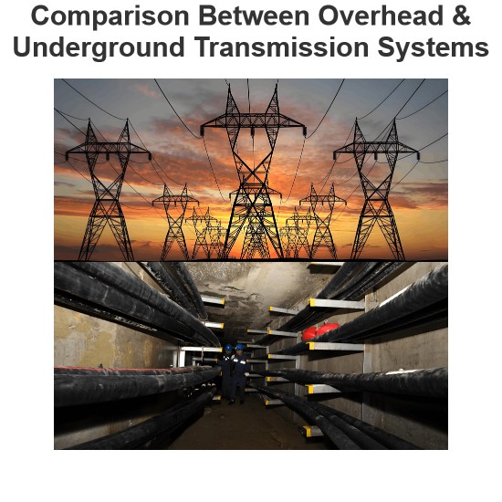
Key Differences and Comparison Between Underground and Overhead Power Transmission & DistributionPublic SafetyIn terms of public safety, underground systems outperform overhead transmission systems. With all transmission and distribution components buried, underground setups minimize risks from obstacles and external interference. Additionally, they are less susceptible to environmental factors like wind, storms, and heavy rain, making them inherently more secure.Initial CostUnderground syst
05/30/2025
Consult
Tip


