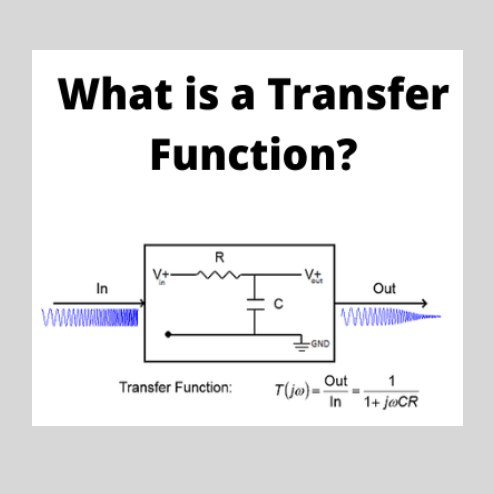
A transfer functionrepresents the relationship between the output signal of a control system and the input signal, for all possible input values. A block diagram is a visualization of the control system which uses blocks to represent the transfer function, and arrows which represent the various input and output signals.For any control system, there exists a reference input known as excitation or cause which operates through a transfer operation (i.e. the transfer function) to produce an effect r
03/29/2024
Consult
Tip
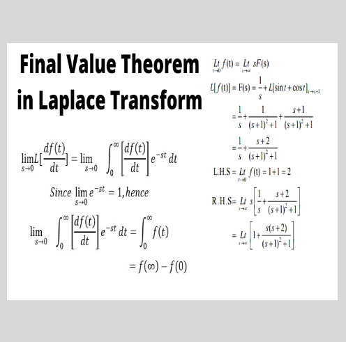
In the solution of Networks, Transient, and Systems sometimes we may not be interested in finding out the entire function of time f(t) from it’s Laplace Transform F(s), which is available for the solution. It is very interesting to find that we can find the first value or last value of f(t) or it’s derivatives without having to find out the entire function f(t). We will be interested in finding out final values and it’s derivatives in this article.For the sake of example:If F(s) is given, we wou
03/29/2024
Consult
Tip
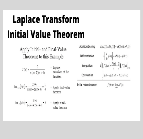
Initial Value Theorem is one of the basic properties of Laplace transform. It was given by prominent French Mathematical Physicist Pierre Simon Marquis De Laplace. He made crucial contributions in the area of planetary motion by applying Newton’s theory of Gravitation. His work regarding the theory of probability and statistics is considered pioneering and this influenced a whole new generation of Mathematician. Laplace is one among the 72 people to have their name engraved on the Eiffel Tower.I
03/29/2024
Consult
Tip
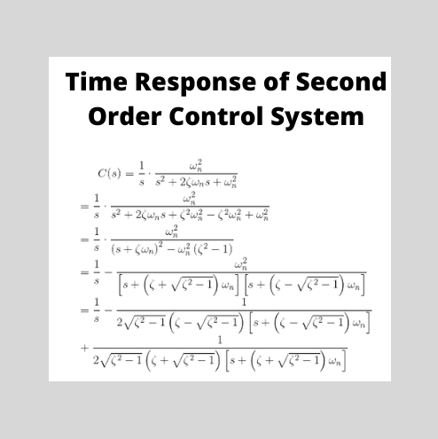
The order of a control system is determined by the power of ‘s’ in the denominator of its transfer function.If the power of s in the denominator of the transfer function of a control system is 2, then the system is said to be second order control system.The general expression of the transfer function of a second order control system is given asHere, ζ and ωn are the damping ratio and natural frequency of the system, respectively (we will learn about these two terms in detail later on).Rearrangin
03/29/2024
Consult
Tip
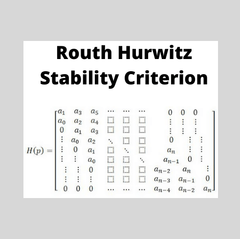
After reading the theory of network synthesis, we can easily say that any pole of the system lies on the right hand side of the origin of the s plane, it makes the system unstable. On the basis of this condition A. Hurwitz and E.J.Routh started investigating the necessary and sufficient conditions of stability of a system. We will discuss two criteria for stability of the system. A first criterion is given by A. Hurwitz and this criterion is also known as Hurwitz Criterion for stability or Routh
03/29/2024
Consult
Tip
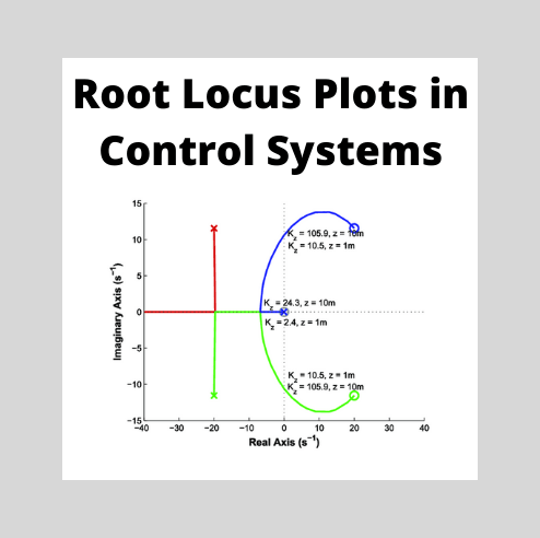
The root locus technique in control system was first introduced in the year 1948 by Evans. Any physical system is represented by a transfer function in the form ofWe can find poles and zeros from G(s). The location of poles and zeros are crucial keeping view stability, relative stability, transient response and error analysis. When the system is put to service stray inductance and capacitance get into the system, thus changes the location of poles and zeros. In root locus technique in control sy
03/29/2024
Consult
Tip

Before I introduce you about the concept of state space analysis of control system, it is very important to discuss here the differences between the conventional theory of control system and modern theory of control system. The conventional control theory is completely based on the frequency domain approach while the modern control system theory is based on time domain approach. In the conventional theory of control system we have linear and time invariant single input single output (SISO) syste
03/29/2024
Consult
Tip
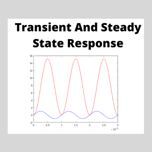
When we study the analysis of the transient state and steady state response of control system it is very essential to know a few basic terms and these are described below.Standard Input Signals : These are also known as test input signals. The input signal is very complex in nature, it is complex because it may be a combination of various other signals. Thus it is very difficult to analyze characteristic performance of any system by applying these signals. So we use test signals or standard inpu
03/29/2024
Consult
Tip

What is a Bode Plot?A Bode plot is a graph commonly used in control system engineering to determine the stability of a control system. A Bode plot maps the frequency response of the system through two graphs – the Bode magnitude plot (expressing the magnitude in decibels) and the Bode phase plot (expressing the phase shift in degrees).Bode plots were first introduced in the 1930s by Hendrik Wade Bode while he was working at Bell Labs in the United States. Although Bode plots offer a relatively s
03/29/2024
Consult
Tip
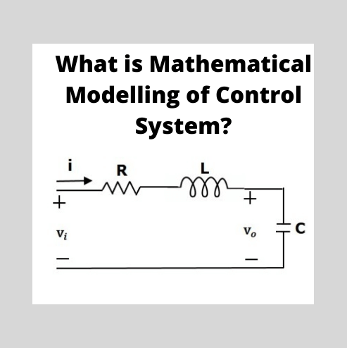
Mathematical Modelling of Control SystemThere are various types of physical systems, namely we have: Mechanical systems Electrical systems Electronic systems Thermal systems Hydraulic systems Chemical systemsFirst off we need to understand – why do we need to model these systems in the first place? Mathematical modeling of a control system is the process of drawing the block diagrams for these types of systems in order to determine their performance and transfer functions.Now let us describe the
03/29/2024
Consult
Tip


