Solid-state transformers (SST) offer high efficiency, reliability, and flexibility, making them suitable for a wide range of applications: Power Systems: In the upgrade and replacement of traditional transformers, solid-state transformers show significant development potential and market prospects. SSTs enable efficient, stable power conversion along with intelligent control and management, helping to enhance the reliability, adaptability, and intelligence of power systems. Electric Vehicle (EV)
10/27/2025
Consult
Tip
Solid-State Transformers (SST): The Future of Smart Power ConversionSolid-state transformers (SSTs), also known as smart transformers, Power Electronic Transformers (PETs), or Electronic Power Transformers (EPTs), represent a transformative advancement in electrical power systems. Unlike conventional transformers, SSTs leverage power electronic converters, high-frequency magnetic components, and intelligent control systems to deliver not only voltage transformation but also advanced grid managem
10/27/2025
Consult
Tip
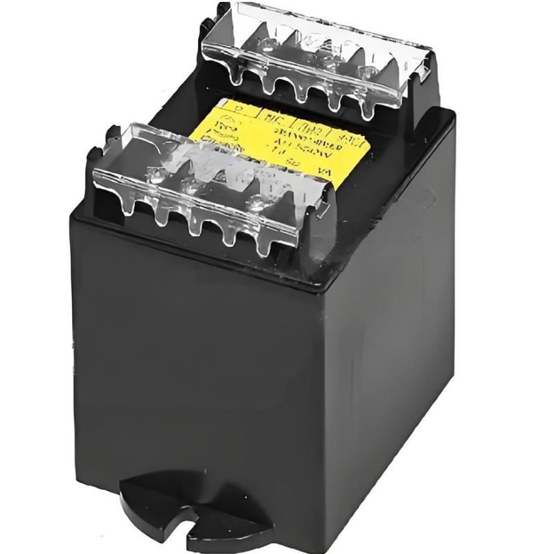
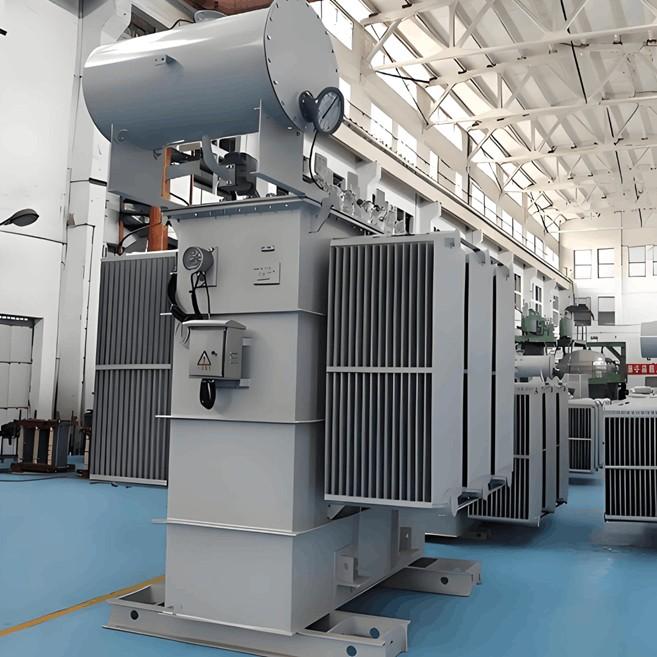
ransformer Capacity Selection: Ensuring Reliable and Efficient Power System OperationTransformer capacity refers to the apparent power at the transformer’s main tap position. The value indicated on the nameplate is known as the rated capacity, typically expressed in kilovolt-amperes (kVA). In practical operation, improperly sized transformers can lead to either under-loading (due to oversizing) or overloading/overcurrent conditions, which may result in equipment overheating, reduced efficiency,
10/27/2025
Consult
Tip
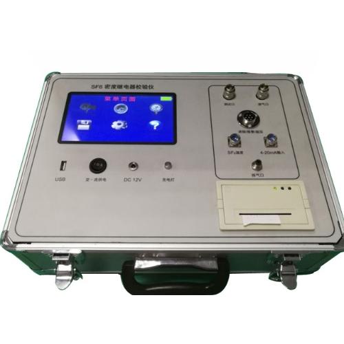
IntroductionSF6 gas is widely used as an insulating and arc-quenching medium in high-voltage and extra-high-voltage electrical equipment due to its excellent insulation, arc-extinguishing properties, and chemical stability. The insulation strength and arc-quenching capability of electrical equipment depend on the density of SF6 gas. A decrease in SF6 gas density can lead to two main hazards: Reduced dielectric strength of the equipment; Decreased interrupting capacity of circuit breakers.Additio
10/27/2025
Consult
Tip

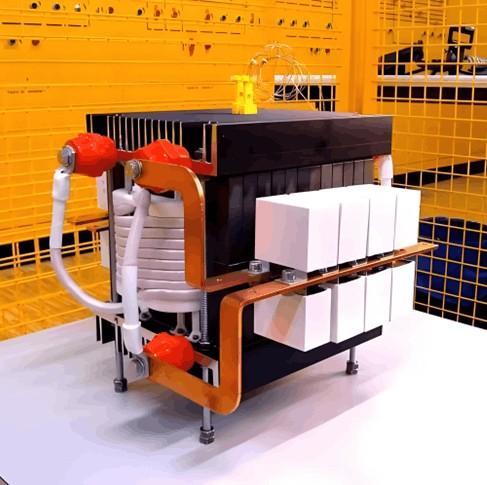
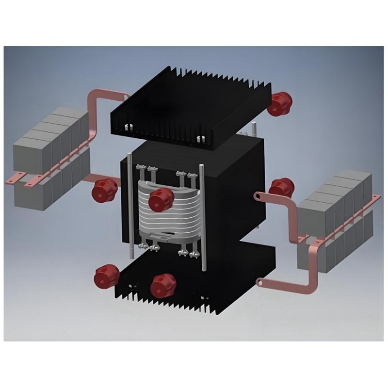
Solid State Transformer (SST)A Solid State Transformer (SST) is a power conversion device that uses modern power electronics technology and semiconductor devices to achieve voltage transformation and energy transfer.Key Differences from Conventional Transformers Different Operating Principles Conventional Transformer: Based on electromagnetic induction. It changes voltage through electromagnetic coupling between primary and secondary windings via an iron core. This is essentially a direct "mag
10/25/2025
Consult
Tip
1.Rectifier Transformer: Principle and OverviewA rectifier transformer is a specialized transformer designed to supply rectifier systems. Its working principle is the same as that of a conventional transformer — it operates based on electromagnetic induction and is used to transform alternating voltage. A typical transformer has two electrically isolated windings — primary and secondary — wound around a common iron core.When the primary winding is connected to an AC power source, alternating cur
10/25/2025
Consult
Tip

Leakage in Hydraulic Operating MechanismsFor hydraulic mechanisms, leakage can cause short-term frequent pump starting or excessively long re-pressurization time. Severe internal oil seepage in valves may lead to pressure loss failure. If hydraulic oil enters the nitrogen side of the accumulator cylinder, it can cause abnormal pressure rise, which affects the safe operation of SF6 circuit breakers.Apart from failures caused by damaged or abnormal pressure detection devices and pressure component
10/25/2025
Consult
Tip
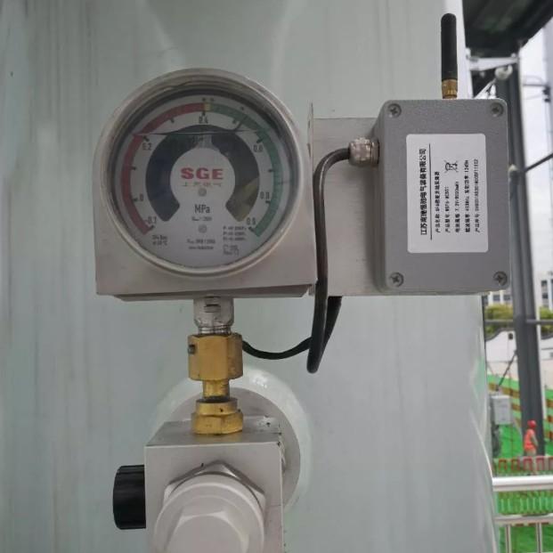
1. BackgroundSF6 electrical equipment has been widely applied in power utilities and industrial enterprises, significantly advancing the development of the power industry. Ensuring the reliable and safe operation of SF6 equipment has become a critical task for power departments.The arc-quenching and insulating medium in SF6 equipment is SF6 gas, which must remain sealed—any leakage compromises the reliability and safety of the equipment. Therefore, monitoring the SF6 gas density is essential.Cur
10/25/2025
Consult
Tip
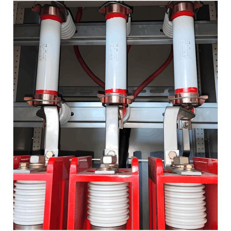
I. Fuse Structure and Root Cause AnalysisSlow Fuse Blowing:From the design principle of fuses, when a large fault current passes through the fuse element, due to the metal effect (certain refractory metals become fusible under specific alloy conditions), the fuse first melts at the soldered tin ball. The arc then rapidly vaporizes the entire fuse element. The resulting arc is quickly extinguished by quartz sand.However, due to harsh operating environments, the fuse element may age under the comb
10/24/2025
Consult
Tip
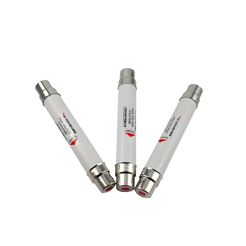
Common Causes of Fuse BlowingCommon reasons for fuse blowing include voltage fluctuations, short circuits, lightning strikes during storms, and current overloads. These conditions can easily cause the fuse element to melt.A fuse is an electrical device that interrupts the circuit by melting its fusible element due to heat generated when current exceeds a specified value. It operates on the principle that, after an overcurrent persists for a certain period, the heat produced by the current melts
10/24/2025
Consult
Tip


