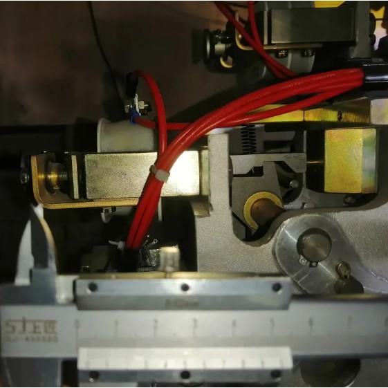
The CT20 series operating mechanism is a classic design. One common cause of failure to close is an improperly adjusted, overly short stroke of the closing solenoid. The rated stroke is approximately 5mm. However, due to vibration or incorrect adjustment after maintenance, the stroke may decrease to around 3mm, potentially causing the mechanism to fail to operate. If the control system continuously issues a closing command under such conditions, the solenoid remains energized, which can lead to
10/23/2025
Consult
Tip
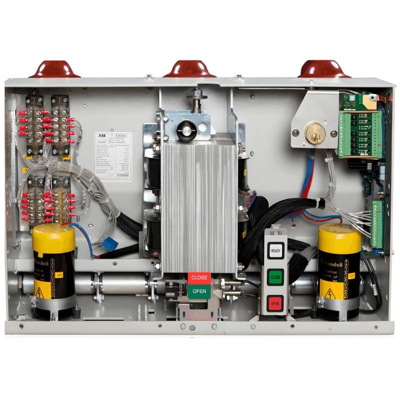
The performance of circuit breaker operating mechanisms is decisive for reliable and safe power supply. While various mechanisms each have their advantages, the emergence of a new type does not completely replace traditional ones. For example, despite the rise of eco-friendly gas insulation, solid insulation ring main units still hold about 8% of the market, showing new technologies rarely fully displace existing solutions.The permanent magnet actuator (PMA) consists of permanent magnets, a clos
10/23/2025
Consult
Tip
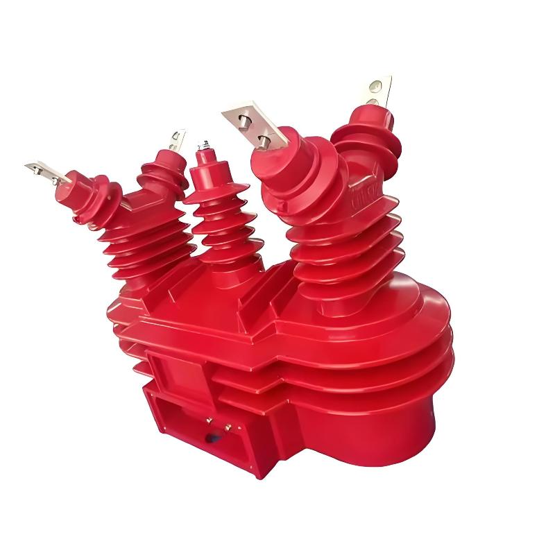
Combined Instrument Transformers: Technical Requirements and Testing Standards Explained with DataA combined instrument transformer integrates a voltage transformer (VT) and a current transformer (CT) into a single unit. Its design and performance are governed by comprehensive standards covering technical specifications, testing procedures, and operational reliability.1. Technical RequirementsRated Voltage:The primary rated voltages include 3kV, 6kV, 10kV, and 35kV, among others. The secondary v
10/23/2025
Consult
Tip
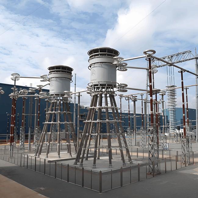
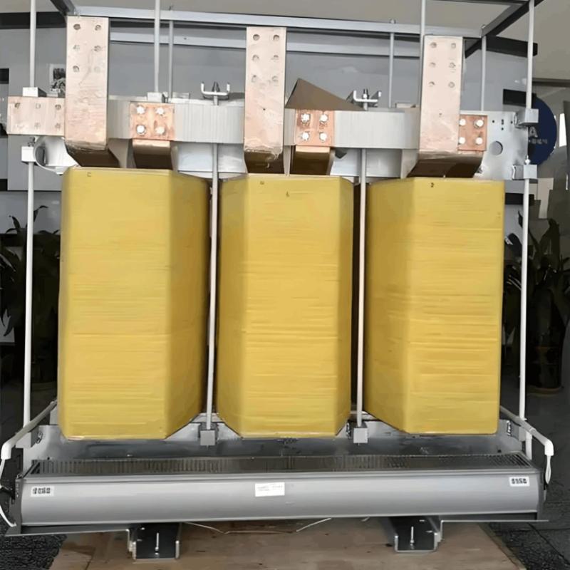
Reactor (Inductor): Definition and TypesA reactor, also known as an inductor, generates a magnetic field within the surrounding space when current flows through a conductor. Therefore, any current-carrying conductor inherently possesses inductance. However, the inductance of a straight conductor is small and produces a weak magnetic field. Practical reactors are constructed by winding the conductor into a solenoid shape, known as an air-core reactor. To further increase inductance, a ferromagnet
10/23/2025
Consult
Tip
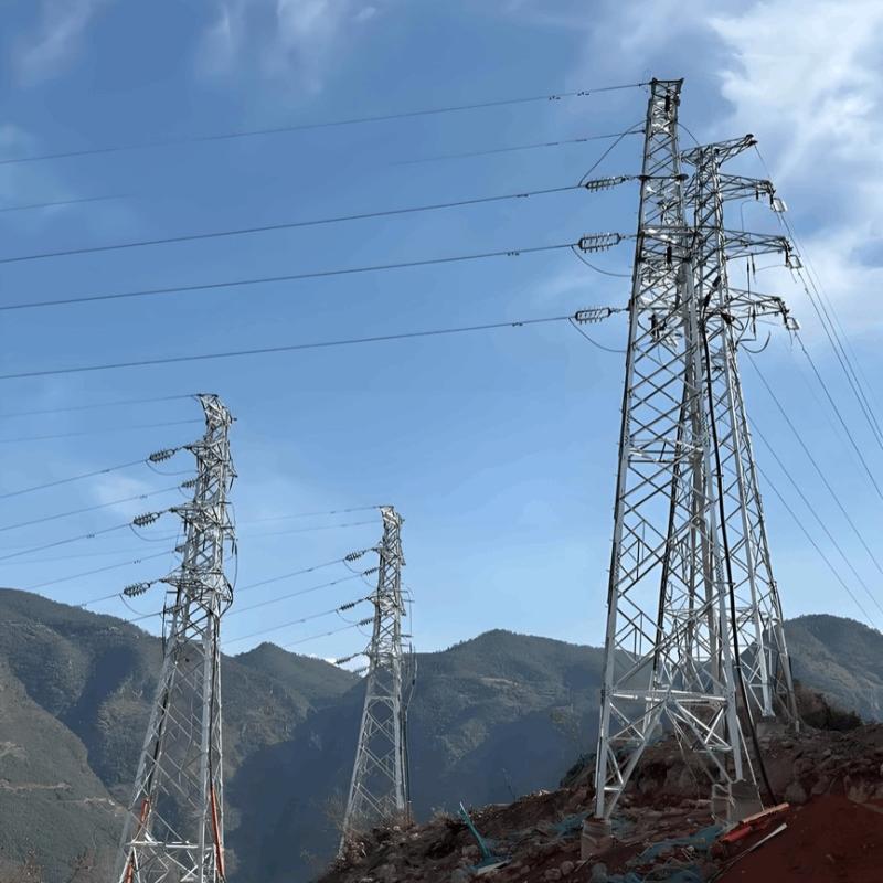
Distribution Lines: A Key Component of Power SystemsDistribution lines are a major component of power systems. On the same voltage-level busbar, multiple distribution lines (for input or output) are connected, each with numerous branches arranged radially and linked to distribution transformers. After being stepped down to low voltage by these transformers, electricity is supplied to a wide range of end users. In such distribution networks, faults such as phase-to-phase short circuits, overcurre
10/23/2025
Consult
Tip
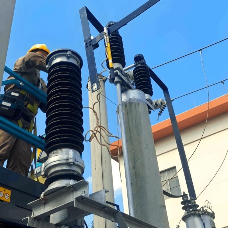
An On-Line Testing Method for Surge Arresters at 110kV and BelowIn power systems, surge arresters are critical components that protect equipment from lightning overvoltage. For installations at 110kV and below—such as 35kV or 10kV substations—an on-line testing method effectively avoids the economic losses associated with power outages. The core of this method lies in using online monitoring technology to evaluate arrester performance without interrupting system operation.The test principle is b
10/23/2025
Consult
Tip
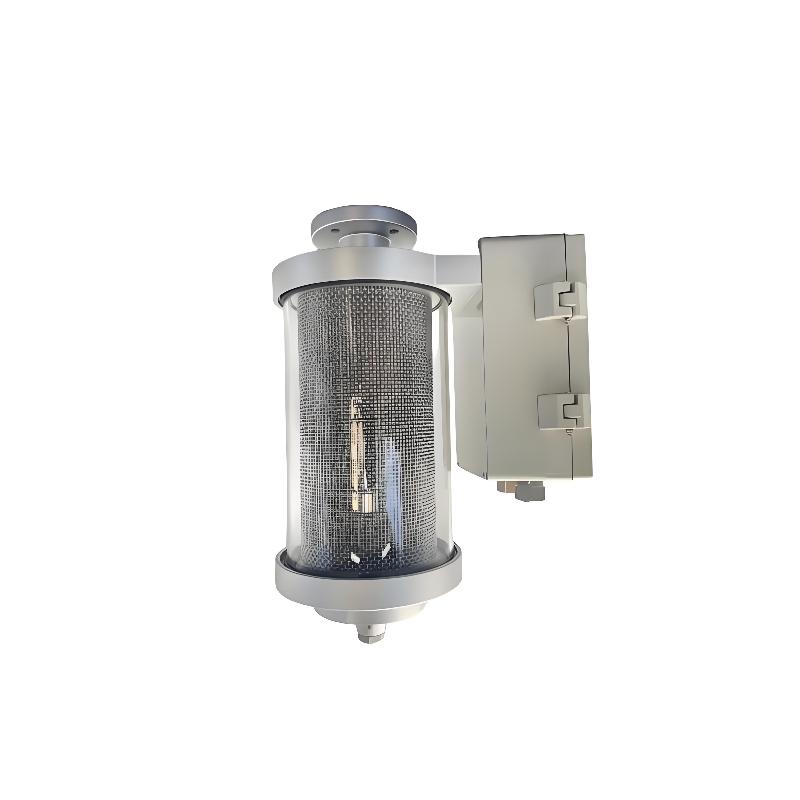
Maintenance-Free Moisture Absorption Technology for Oil-Immersed TransformersIn traditional oil-filled transformers, the temperature control system causes thermal expansion and contraction of insulating oil, requiring the sealing gel chamber to absorb significant moisture from the air above the oil surface. The frequency of manual silica gel replacement during patrols directly impacts equipment safety—delayed replacement can easily lead to oil degradation. Maintenance-free moisture absorbers rev
10/23/2025
Consult
Tip
Medium-voltage DC (MVDC) transformers have a wide range of applications in modern industry and power systems. The following are some key application areas for MVDC transformers: Power Systems: MVDC transformers are commonly used in high-voltage direct current (HVDC) transmission systems to convert high-voltage AC into medium-voltage DC, enabling efficient long-distance power transmission. They also contribute to grid stability control and power quality improvement. Industrial Applications: In in
10/23/2025
Consult
Tip
Medium-voltage direct current (MVDC) technology is a key innovation in power transmission, designed to overcome limitations of traditional AC systems in specific applications. By transmitting electrical energy via DC at voltages typically ranging from 1.5 kV to 50 kV, it combines the long-distance transmission advantages of high-voltage DC with the flexibility of low-voltage DC distribution. Against the backdrop of large-scale renewable integration and new power system development, MVDC is emerg
10/23/2025
Consult
Tip
Analysis and Handling of DC System Grounding Faults in SubstationsWhen a DC system grounding fault occurs, it can be classified as single-point grounding, multi-point grounding, loop grounding, or reduced insulation. Single-point grounding is further divided into positive-pole and negative-pole grounding. Positive-pole grounding may cause misoperation of protection and automatic devices, while negative-pole grounding may lead to failure to operate (e.g., relay protection or tripping devices). On
10/23/2025
Consult
Tip


