
With the expansion of power system scale and the cableization process of urban power grids, the capacitive current in 6kV/10kV/35kV power grids has significantly increased (generally exceeding 10A). As power grids at this voltage level mostly adopt neutral ungrounded operation mode, and the distribution voltage side of main transformers is usually in delta connection, lacking a natural grounding point, the arc during ground faults cannot be reliably extinguished, necessitating the introduction o
06/11/2025
Consult
Tip
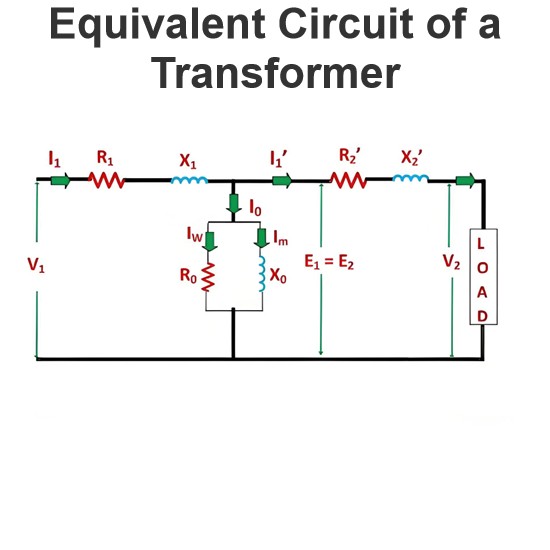
The equivalent circuit diagram of any device can be extremely useful for predicting how the device will behave under different operating conditions. It is essentially a circuit - based depiction of the equations that describe the device's performance.The simplified equivalent circuit of a transformer is constructed by representing all of the transformer's parameters on either the secondary side or the primary side. The equivalent circuit diagram of the transformer is presented below:Let the equi
06/03/2025
Consult
Tip
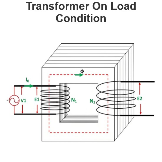
Transformer Operation Under Load ConditionsWhen a transformer is under load, its secondary winding connects to a load, which can be resistive, inductive, or capacitive. A current I2 flows through the secondary winding, with its magnitude determined by the terminal voltageV2and load impedance. The phase angle between the secondary current and voltage depends on the load characteristics.Explanation of Transformer Load OperationThe operational behavior of a transformer under load is detailed as fol
06/03/2025
Consult
Tip
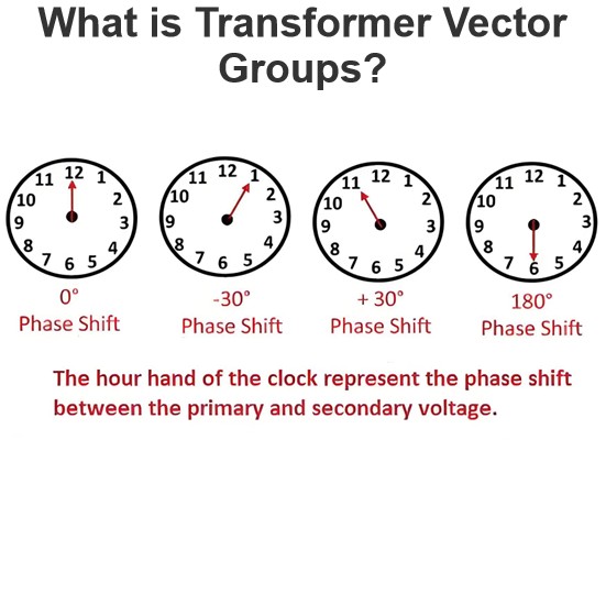
Transformer Vector Group DefinitionThe transformer vector group denotes the phase difference between the primary and secondary sides of a transformer, while also defining the arrangement of high-voltage and low-voltage windings in three-phase transformers. Vector groups are determined by the connection configurations of three-phase transformers, which can be categorized into four main groups based on the phase difference between corresponding line voltages of the high-voltage and low-voltage sid
06/02/2025
Consult
Tip

Definition of Parallel Magnetic CircuitA parallel magnetic circuit is defined as a magnetic pathway with two or more branches for magnetic flux, analogous to a parallel electric circuit. Such circuits feature multiple flux paths with varying cross-sectional areas and materials, each potentially composed of different magnetic components.Parallel Magnetic Circuit AnalysisThe figure above depicts a parallel magnetic circuit, where a current-carrying coil is wound around the central limb AB. This co
05/28/2025
Consult
Tip

Background of Transformer EMF Equation DerivationWhen a sinusoidal voltage is applied to the transformer's primary winding, an alternating flux ϕmis induced in the iron core. This sinusoidal flux links both primary and secondary windings, with its functional form described by a sine function.Mathematical Derivation of Flux Rate of ChangeThe following outlines the derivation of the transformer's EMF equation, with defined parameters: ϕm: Maximum flux (Weber) f: Supply frequency (Hz) N1: Number of
05/28/2025
Consult
Tip

No-Load Operation of TransformerWhen a transformer operates under no-load conditions, its secondary winding is open-circuited, eliminating load on the secondary side and resulting in zero secondary current. The primary winding carries a small no-load currentI0, comprising 2 to 10% of the rated current. This current supplies iron losses (hysteresis and eddy current losses) in the core and minimal copper losses in the primary winding.The lag angle ofI0is determined by transformer losses, with the
05/28/2025
Consult
Tip

Transformer Construction and Key ComponentsA transformer primarily comprises a magnetic circuit, electric circuit, dielectric circuit, tank, and auxiliary components. Its core elements are the primary/secondary windings and a steel core, with the core constructed from silicon steel to form a continuous magnetic path. Transformer cores are typically laminated to minimize eddy current losses.Magnetic CircuitThe magnetic circuit consists of the core and yoke, providing a pathway for magnetic flux.
05/28/2025
Consult
Tip

Voltage Regulation Definition and SignificanceDefinitionVoltage regulation is defined as the change in magnitude between the sending-end and receiving-end voltages of a transformer. This parameter quantifies the transformer's capability to maintain steady output voltage under varying load conditions.When a transformer operates with a constant supply voltage, its terminal voltage fluctuates in response to load variations and the load's power factor.Mathematical RepresentationVoltage regulation is
05/27/2025
Consult
Tip

Insulation Systems in Oil-Immersed TransformersThe most prevalent insulation for high-voltage windings in modern transformers consists of enamel-coated conductors with kraft paper interlayer insulation.Low-voltage busbars may employ bare conductors with paper insulation between layers.Notably, paper wrapping on busbar conductors is being gradually replaced by synthetic polymer coatings or synthetic fabric wraps.The adoption of aluminum wires, busbars, and strip conductors with enamel coatings pr
05/23/2025
Consult
Tip


